6-5. AM CIRCUIT (model 8022)
The AM circuit is constructed on the same board as the
output amplifier. The complete assembly, which includes
the above sections plus the AM circuit, is unique to the
model 8022. In the following, only the section pertaining
to the amplitude modulation circuit is described. The rest
of the circuits are identical to those available on the model
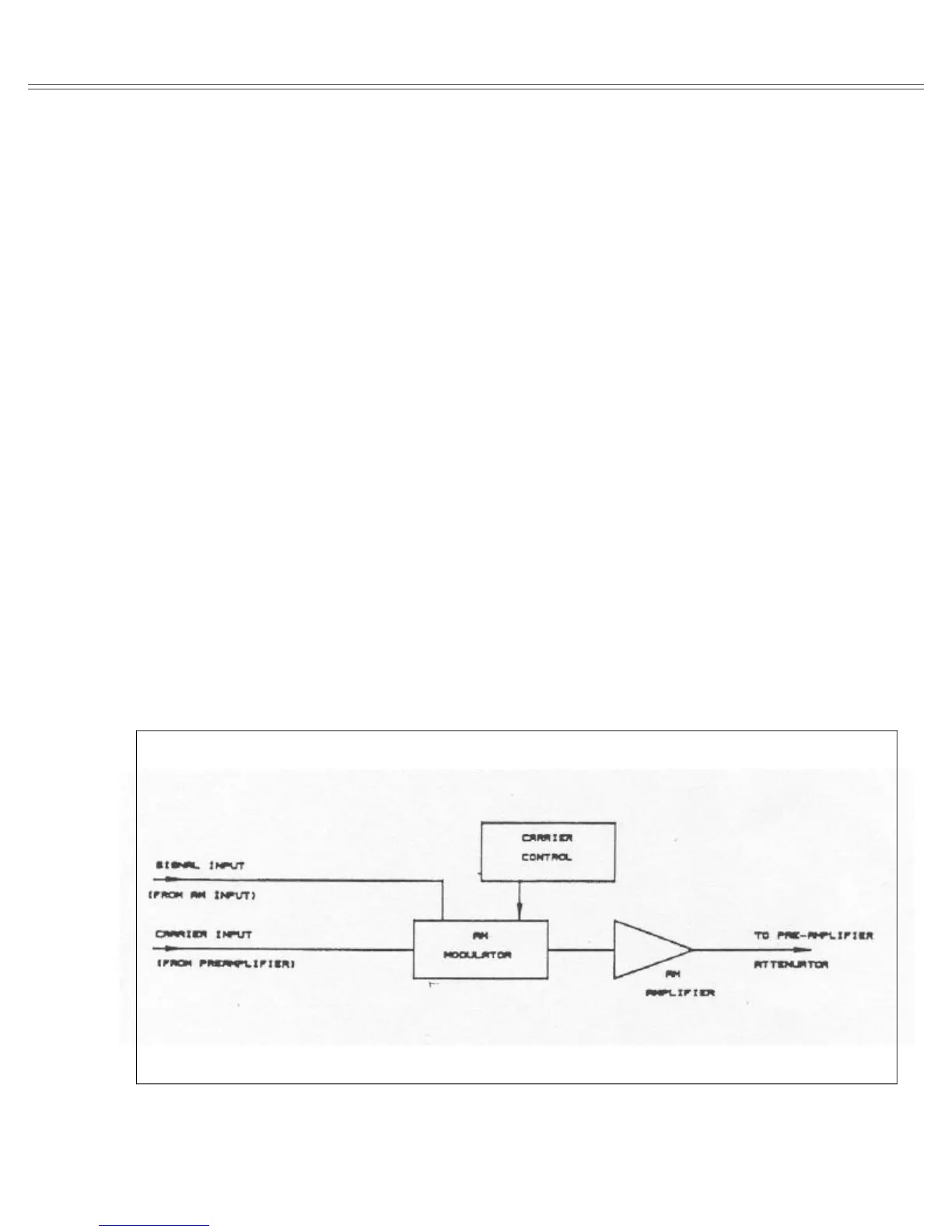
8020. Figure 6-9 is a functional block diagram. For com-
plete and detailed schematics, refer to the back of this man-
ual.
The modulator is composed of transistor arrays U24
and U25, transistors Q47, Q48 and Q56 and their associ-
ated components. The carrier is applied to the base of Q47.
The modulating signal is applied through R130, U25,
R131 and R174 to the modulator circuit. Carrier level is
controlled by U21. U21 receives serial data from the CPU
and converts this data to parallel information for driving
U22.
AM AMPLIFIER - The AM amplifier is a differential
amplifier consisting of transistors Q49 through Q54 and
their associated components. The output, at the junction of
R163 and R167 is fed through a relay K4 to the pre-ampli-
fier circuit.
6-6. DIGITAL CIRCUITRY
Model 8020 operation is supervised by the internal micro-
processor (CPU). The CPU controls parameter selection
process, front panel switching, the displayed read-out and
IEEE operation. All of these tasks are performed under
software supervision. This section briefly describes the
operation of the various sections of the microprocessor
and its associated digital circuitry. A simplified block dia-
gram is included for user reference. For more complete
circuit details refer to the digital schematics at the end of
this manual.
Circuit operation centers around the microprocessor
unit (CPU) U5. The CPU is an 8-bit microprocessor capa-
ble of directly addressing up to 64K bytes of program
memory (ROM) and up to another 64K bytes of data mem-
ory (RAM). The microprocessor works with a 10 Mhz
clock which is divided by U6 to provide clocks for the vari-
ous sections of the instrument. Software for the CPU is
contained in one EPROM U8 containing 32K bytes of
memory space. Temporary storage is provided by RAM
U9 which can store up to 2K bytes of information.
6-6-1. Display And Keyboard Interface
Interfacing between the CPU, the keyboard and the dis-
play is performed by the Keyboard/Display interface U2.
The information for the seven segment LEDs is sent
through buffer U1 and limiting resistors RN1. U1 multi-
plex the digits and LED and drive the high current transis-
Figure 6-8. AM Circuit Functional Block Diagram.
Model 8020 Theory Of Operation
Page 6-9