TB9400/TN9275 Installation and Operation Description 31
© Tait International Limited May 2023
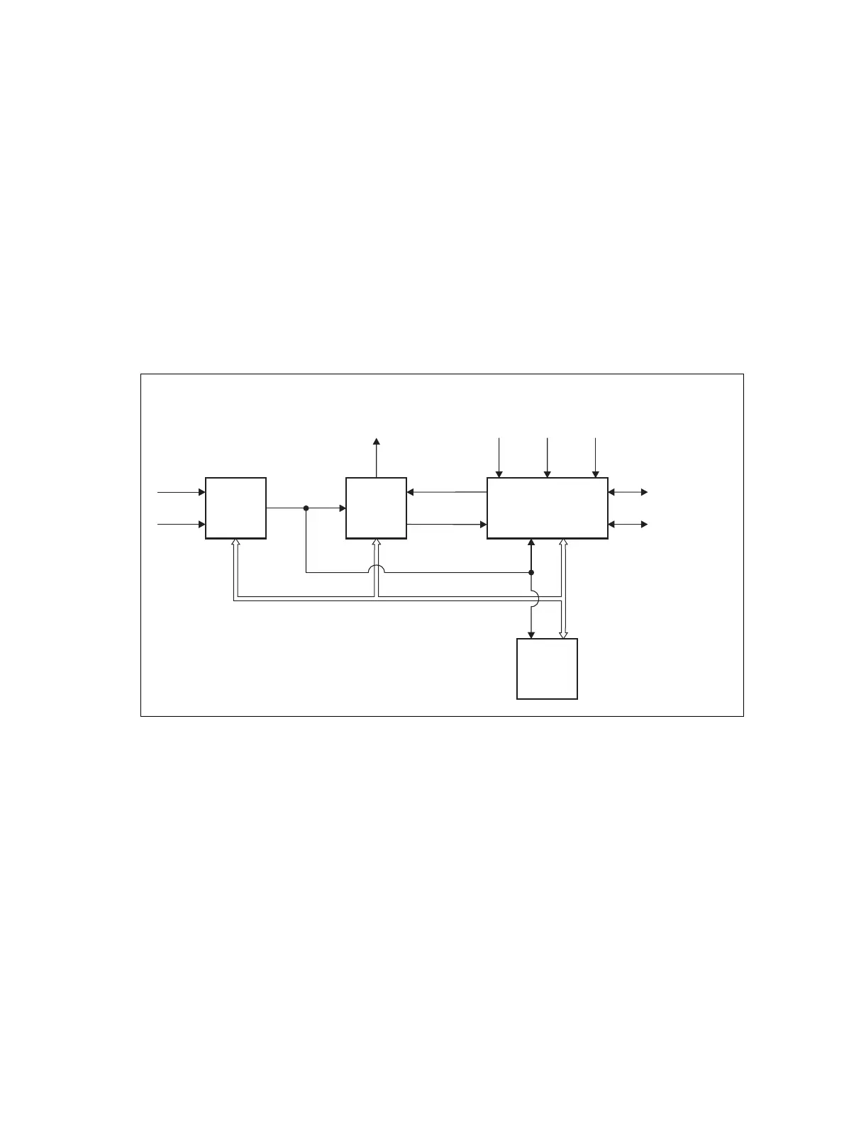
1.8 Theory of Operation
The reciter receives RF signals from its RF input (antenna), and outputs this
to the PA, along with a PA key signal. The PA sends an RF feedback signal
to the reciter for linearization and power control purposes. The reciter also
receives signals from, and sends signals to, the system interface, the
Ethernet interface, and the front panel (see Figure 1.4).
A system control bus interconnects the modules and carries alarm and
control signaling between the reciter and the other modules (refer to
“Intermodule Communications” on page 34 for more details).
The Ethernet interface carries VoIP and also allows maintainer access via a
web browser.
Figure 1.4 Base station high-level diagram
Reciter
PMU
PA
RF To
Antenna
RF From
Antenna
1PPS
External
Reference
Frequency
AC Input
DC Input
28VDC
System Control Bus
RF+PAKey
RF Feedback
System Input
and Output
Ethernet Interface
to Network
Front
Panel
A receive-only base station has a receiver instead of a reciter,
and does not have a PA.

 Loading...


