54 Operation TB9400/TN9275 Installation and Operation
© Tait International Limited May 2023
3.2.3 PMU
The only controls on the PMU are the on/off switches on the rear panel for
the AC and DC modules, and the indicator LEDs visible through a slot in
its front panel.
Warning The AC and DC module on/off switches do not totally
isolate the internal circuitry of the PMU from the AC or DC power
supplies. You must disconnect the AC and DC supplies from the
PMU before dismantling or carrying out any maintenance.
AC Module On/Off
Switch
This switch turns the AC input to the PMU on and off. Note that this switch
breaks only the phase circuit, not the neutral.
The AC On/Off switch protrudes whether on or off.
DC Module On/Off
Switch
This switch turns the DC output from the PMU on and off. Note that this
switch does not disconnect power from the DC converter itself. It disables
the converter by switching off its control circuitry. Even when the DC
converter is off, the DC input is still connected to its power circuitry.
The switch is recessed to prevent the DC module being accidentally
switched off.
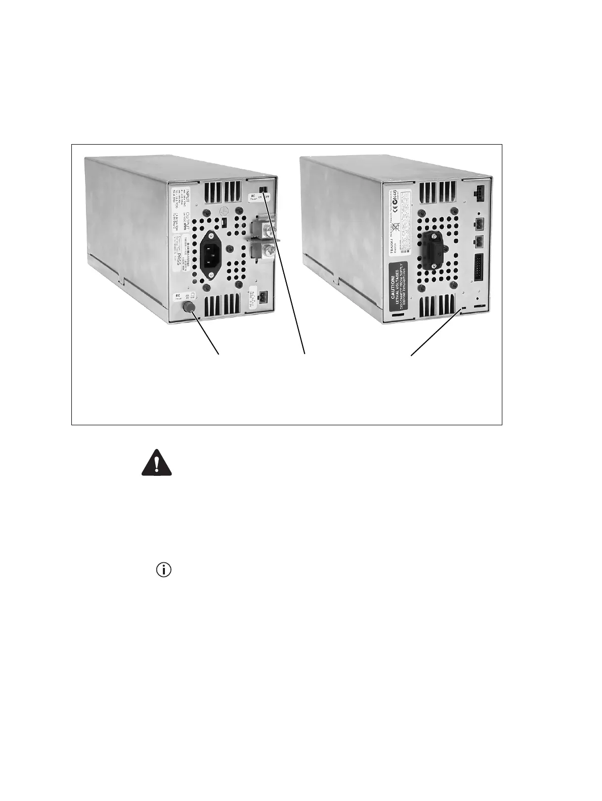
Figure 3.5 Operating controls on the PMU
b
AC module on/off switch
d
indicator LEDs
c
DC module on/off switch

 Loading...


