TB9400/TN9275 Installation and Operation Description 23
© Tait International Limited May 2023
1.5 Mechanical Assembly
This section illustrates the main mechanical components of the base
station.
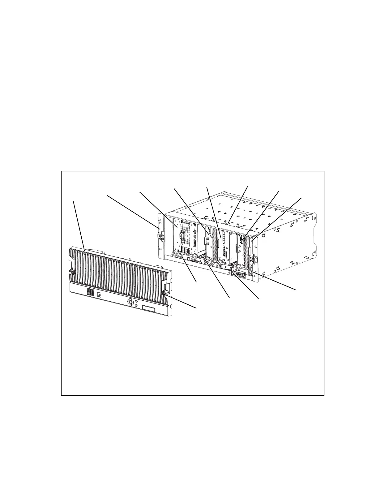
Figure 1.1 below shows the configuration for a typical dual 50W base
station. The subrack has six slots, numbered from right to left as viewed
from the front of the subrack. The PMU occupies slots 5 and 6, with the
reciter and PA pairs to the right of it in slots 1 to 4. Each PA is mounted
vertically with its heatsink facing its associated reciter. The PMU and each
reciter/PA pair have their own cooling fans.
The front panel can be easily removed from the subrack by undoing two
quick-release fasteners. Refer to “Replacing Modules” on page 123 for
more details.
.
Figure 1.1 Mechanical assembly - dual 50W base station with front panel
b front panel i reciter 1
c subrack j module retaining clamp
d PMU 1) subrack interconnect board
e PA 2 1! plastic guide rail
f reciter 2 1@ subrack interconnect board retaining clamp
g cable retaining clip 1# front panel fastener
h PA 1