TM8000 Mobile Radio Accessories Manual TMAA01-01 Line-Interface Board 25
March 2004 © Tait Electronics Limited
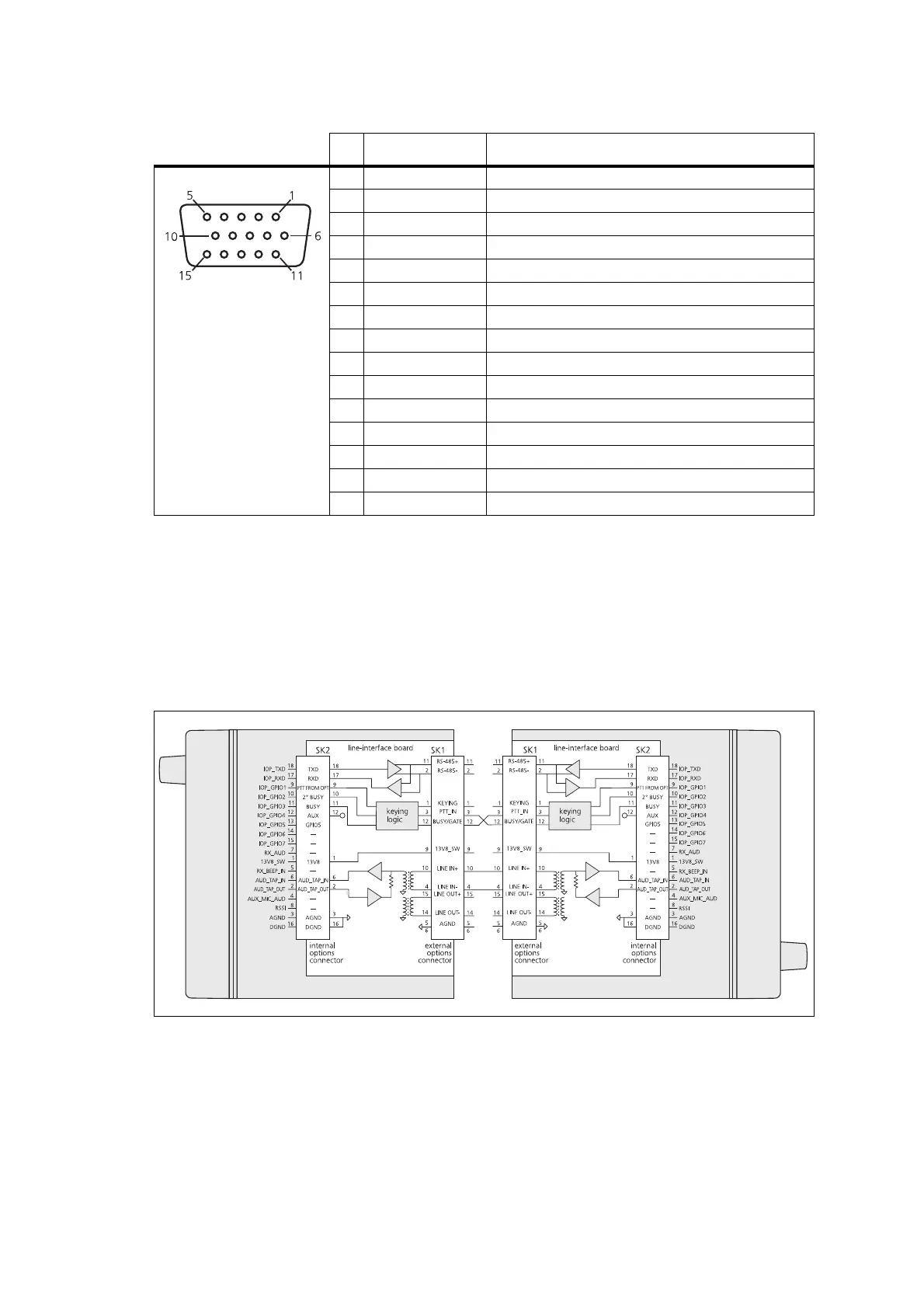
2.6 Line-Interface Board Application
The following diagram shows the control of two radios operated together,
crossband or repeater linked.
Table 2.8 External options connector (SK1) - pins and signals
Pin Signal Description
1 KEYING signal line keying
2 —
not connected
11 —
not connected
3 PTT-IN bi-directional keying input
4 4W_LINE_IN - 4-wire line in negative
10 4W_LINE_IN +
4-wire line in positive
5 GND ground
6 GND ground
7 —
not connected
8 — not connected
9 13V8 FROM RADIO switched 13.8V supply from the radio
12 BUSY/GATE Busy or receiver gate output. 5V CMOS logic level.
13 — not connected
14 4W_LINE_OUT - 4-wire line out negative or 2-wire line in/out negative
15 4W_LINE_OUT + 4-wire line out positive or 2-wire line in/out positive
front view
Figure 2.3 Two radios connected as a repeater/crossband link
 Loading...


