TM8000 Mobile Radio Accessories Manual TMAA02-06 Support Kit for Concealed & Dynamic Microphones 53
March 2004 © Tait Electronics Limited
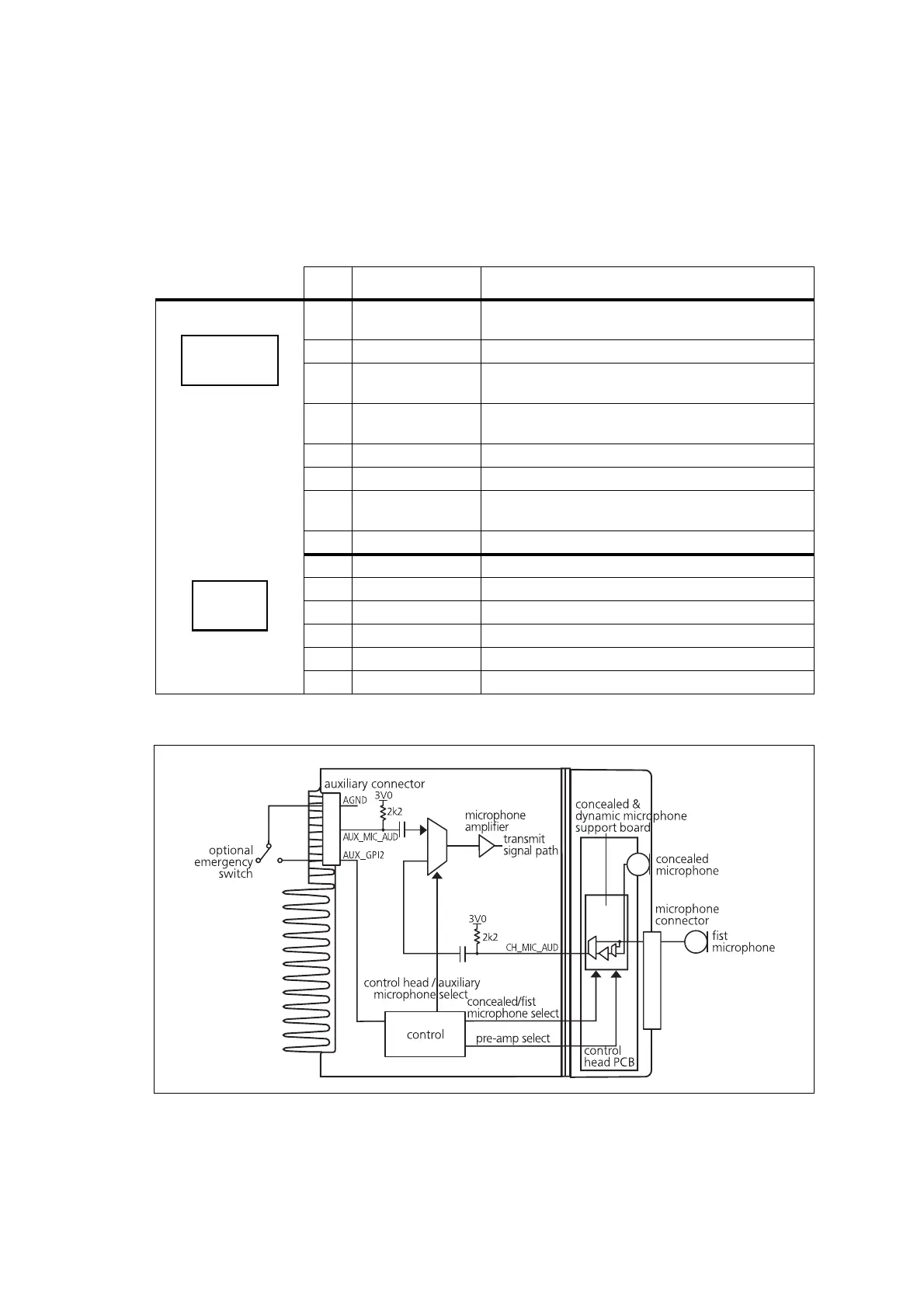
5.3 Interface Specification
The following table and diagram summarizes the signals used for the
concealed and dynamic microphone support kit and shows the interface
between the support kit and the radio control head.
Table 5.1 Concealed and dynamic microphone support board - pins and signals
Pin Signal Colour
1 CH_LE SPI latch signal to latch microphone select data into
the concealed and dynamic microphone board
2 D2-D3 data from the control head shift register
3 OE enables the output of the shift register of the audio
switch
4 CH_SPI_CLK SPI clock signal to clock microphone select data into
concealed and dynamic microphone board
5 +13V8_SW power for analogue parts
6 +3V3 power for digital parts
7 RST initialise the concealed and dynamic microphone
board shift register
8 DGND digital ground
1 MIC_AUD_IN-P1 microphone audio from microphone interface
2 MIC_AUD_OUT processed microphone signal output to radio
3 — not connected
4 MIC_AUD_OUT processed microphone signal output to radio
5 MIC+ audio from the concealed microphone
6 AGND analogue ground
BDFH
CEGI
S2 top view
BDF
CEG
S3 top view
Figure 5.1 Concealed and dynamic microphone support kit to radio interface
 Loading...


