TM8000 Mobile Radio Accessories Manual TMAA10-04 Hands-Free Kit 71
March 2004 © Tait Electronics Limited
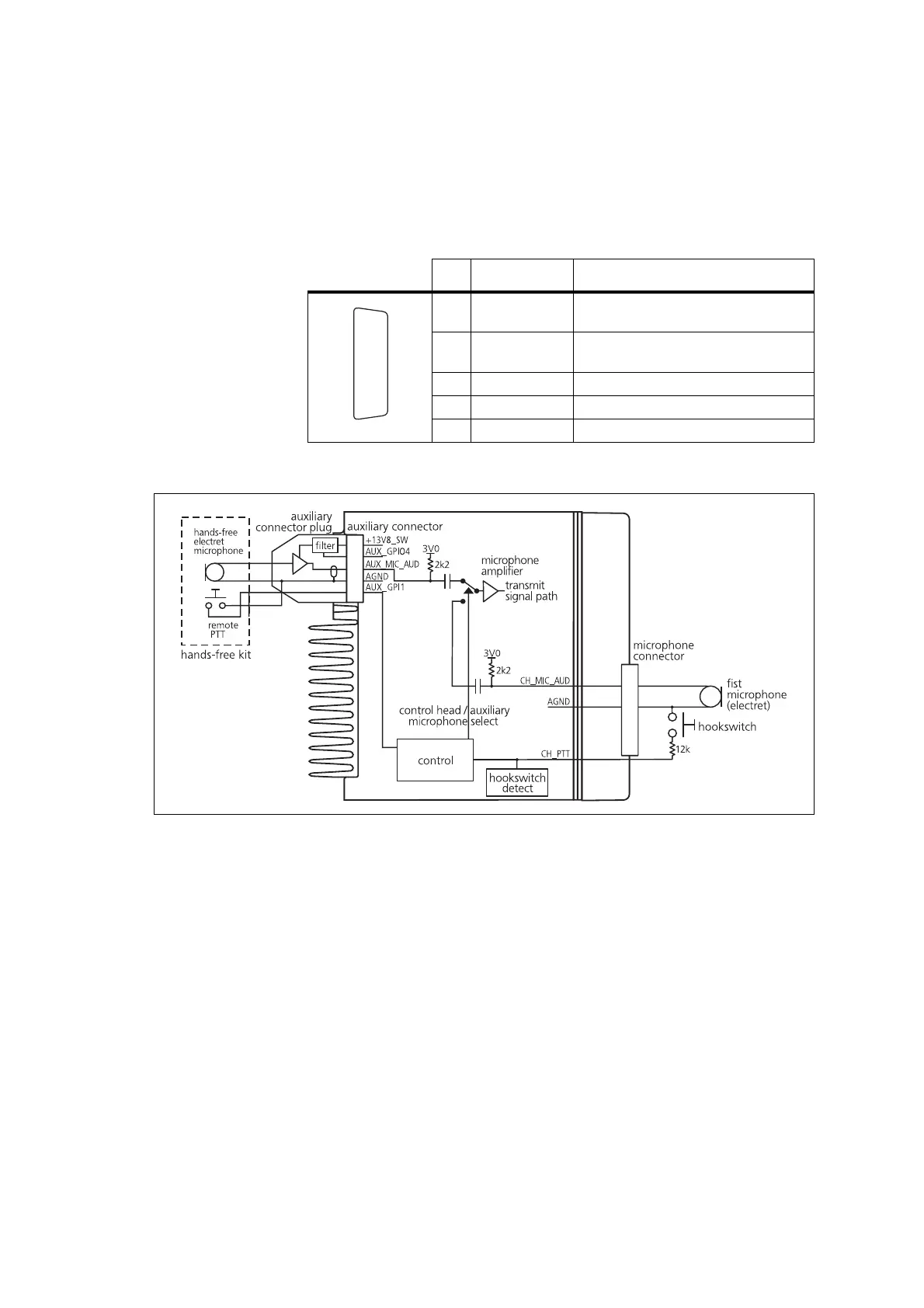
9.3 Interface Specification
The following table and diagram summarizes the signals used for the hands-
free kit on the radio’s auxiliary connector and shows the interface between
the hands-free kit and the radio.
.
9.4 Circuit Description
The hands-free microphone signal is amplified by a pre-amplifier in the
auxiliary connector plug. The power supply to this amplifier is provided by
the +13.8V supply on the auxiliary connector. This supply is filtered and
regulated down to approximately 3.3V. The reference voltage for the
regulator is provided by AUX_GPIO4 line.
The hands-free microphone signal is fed via AUX_MIC_AUD and an input
selector to the radio’s internal microphone amplifier. The microphone input
selected depends on the PTT source used to make the call. If the remote PTT
is used, then AUX_MIC_AUD is selected. If the control head microphone
PTT is used, then CH_MIC_AUD is selected. Test points for all other
auxiliary connections are provided on the auxiliary connector plug PCB to
facilitate the connection of other devices or signals e.g ignition switch signal.
Table 9.3 Auxiliary connector - pins and signals
Pin Signal name Description
8 +13V8_SW
power to hands-free microphone pre-
amplifier
10 AUX_GPIO4
reference voltage to pre-amplifier
regulator
12 AUX_GPI1
PTT signal from hands-free kit
14 AUX_MIC_AUD
microphone audio to the radio
15 AGND
analogue ground
J
B
C
D
E
F
G
H
I
1)
1!
1@
1#
1$
1%
rear view
Figure 9.1 Hands-free to radio interface
 Loading...


