Appendix 9
TW9 101
9 Appendix
9.1 Electrical system
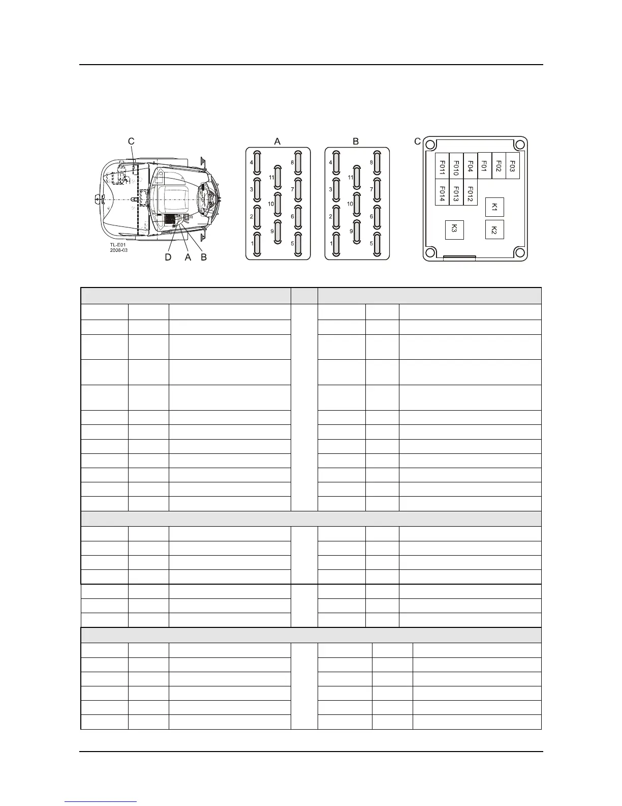
• Fuse box – assignment diagram
Fuses A
Fuses B
Position Amps Assigned to
Position Amps Assigned to
FL 1 15 Heater fan, air conditioning FR 1 15 Working floodlights, front
FL 2 15 Windshield wiper and
washer system, front
FR 2 15 Working floodlight, rear
FL 3 15 Windshield wiper and
washer system, rear
FR 3 10 Direction indicators
FL 4 10 Rotating beacon / interior
light
FR 4 10 Hazard warning switch
FL 5 10 RCS / travel motion alarm FR 5 15 Socket, radio permanent positive
FL 6 10 SRF/air-cushioned seat FR 6 15 Reserve
FL 7 10 Optional: socket attachment FR 7 10 Signal horn
FL 8 10 E-module inputs FR 8 10 Main-beam headlight
FL 9 10 Instrument clusters FR 9 10 Dipped beam
FL 10 10 Radio (ignition lock) FR 10 10 Side light, left
FL 11 10 Refueling pump/SRF FR 11 10 Side light, right
Main fuses and relays in starter box C
F01 50 Pre-fuse/supply F013 5 Reserve
F02 80 Preheating system F014 5 Reserve
F03 30 Power supply control module
F04 50 Starting/shut-off relay K1 Starting relay
F010 15 Cut-out switch K2 Preheater relay
F011 10 Reserve K3 Shut-off relay
F012 5 Reserve
Main fuses and relays in starter box D (underneath right-hand armrest)
FZ1 30 Fans / heating K3 Indicator
FZ2 Optional K5 Fans heating
FZ3 Optional K6 Lighting
FZ4 30 Lighting
FZ5 Optional
FZ6 Optional