INPUT
MODULE
6
Input Select
Q
Trirn
XLR
@
LINE
n
@
frorn Subrnaster Tape
in'
*
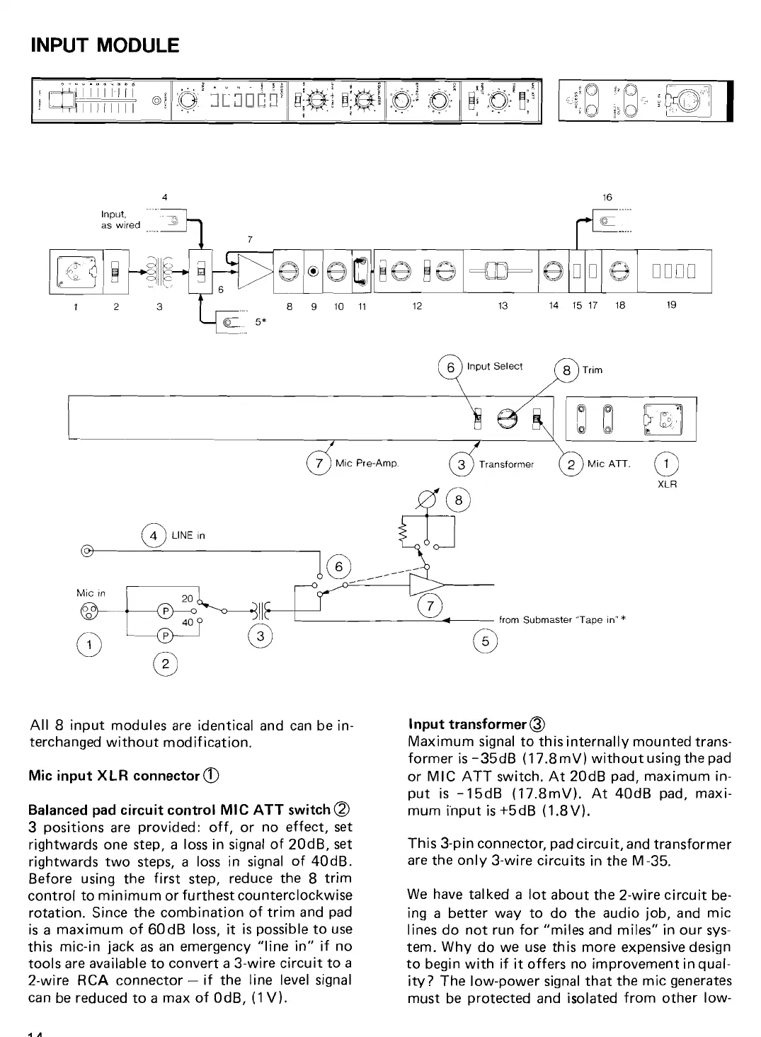
All 8 input modules are identica1 and can be in-
terchanged without modification.
Mic input
XLR
connector
@
Balanced pad circuit contro1 MIC
ATT
switch
a
3 positions are provided: off, or no effect, set
rightwards one step, a loss in signal of
20dB, set
rightwards two steps,
a
loss in signal of 40dB.
Before using the first step, reduce the 8 trim
contro1 to minimum or furthest countercIockwise
rotation. Since the combination of trim and pad
is a maximum of 60
dB loss,
it
is
possible to use
this mic-in jack
as
an emergency "line in" if no
tools are available to convert a 3-wire circuit to
a
2-wire RCA connector
-
if the line level signal
can be reduced to a max of OdB, (1 V).
Input transformer
@
Maximum signal to this internally mounted trans-
former
is
-35dB (17.8mV) without using the pad
or MIC ATT switch. At 20dB pad, maximum
in-
put is -15dB (17.8mV). At 40dB pad, maxi-
mum i'nput
is
+5dB (1.8V).
This 3-pin connector, pad circuit, and transformer
are the only 3-wire circuits in the M-35.
We
have tal ked a lot about the 2-wire circuit be-
ing a better way to do the audio job, and rnic
lines do not run for "miles and miles" in our sys-
tem. Why do we use this more expensive design
to begin with if
it
offers no improvement in qual-
ity? The low-power signal that the rnic generates
must be protected and isolated from other
low-


 To Next Page