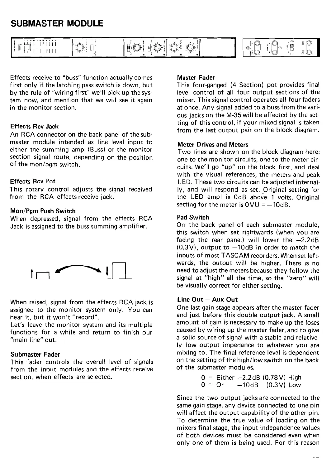
SUBMASTER MODULE
Effects receive to "buss" function actually comes
first only if the latching pass switch
is
down, but
by the rule of "wiring first"
we'll pick up the sys-
tem now, and mention that we will see
it
again
in the monitor section.
Effects Rcv Jack
An RCA connector on the back panel of the
sub-
master module intended as line level input to
either the summing amp
(Buss) or the monitor
section signal route, depending on the position
of the
mon/pgm switch.
Effects Rcv Pot
This rotary control adjusts the signal received
from the RCA effects-receive jack.
Mon/Pgm Push Switch
When depressed, signal from the effects RCA
Jack
is
assigned to the buss summing amplifier.
When raised, signal from the effects RCA jack
is
assigned to the monitor system only. You can
hear
it,
but
it
won't "record".
Let's leave the monitor system and
its
multiple
functions for a while and return to finish our
"main line" out.
Su bmaster Fader
This fader controls the overall level of
signals
from the input modules and the effects receive
section, when effects are selected.
Master Fader
This four-ganged
(4
Section) pot provides final
level control of al1 four output sections of the
mixer. This signal control operates
al1 four faders
at once. Any signal added to a buss from the
vari-
ous jacks on the M-35 will be affected by the
set-
ting of this control, if your mixed signal
is
taken
from the last output pair on the block diagram.
Meter Drives and Meters
Two lines are shown on the block diagram here:
one to the monitor circuits, one to the meter
cir-
cuits. We'll go "up" on the block first, and dea1
with the visual references, the meters and peak
LED. These two circuits
can be adjusted internal-
ly,
and will respond as set. .Original setting for
the LED
ampl
is
OdB above 1 volts. Original
setting for the meter is OVU
=
-10dB.
Pad Switch
On the back panel of each submaster module,
this switch when set rightwards (when you are
facing the rear panel) will lower the
-2.2dB
(0.3V),
output to -10dB in order to match the
inputs of most TASCAM recorders. When
set
left-
wards, the output will be higher. There is no
need to adjust the meters because they follow the
signal at "high"
al1 the time, so the "zero" will
be
visually correct for either setting.
Line Out
-
Aux Out
One last gain stage appears after the master fader
and just before this double output jack. A
small
amount of gain
is
necessary to make up the loses
caused by wiring up the master fader, and to give
a solid source of signal with
a
stable and relative-
ly
low output impedance to whatever you are
mixing to. The
final reference level
is
dependent
on the setting of the
high/low switch on the back
of the submaster modules.
O
=
Either -2.2dB (0.78V) High
O
=
Or -10dB (0.3V) Low
Since the two output jacks are connected to the
same gain stage, any device connected to one pin
will affect the output capability of the other pin.
To determine the true value of loading on the
mixers
final stage, the input independence values
of both devices must be considered even when
only one of them
is
being used. For this reason


 To Next Page