Section 6
6-1
Models 340, 341, 342
Operating Procedure
6
Operating Procedure
Model 341 has been selected to illustrate the pictured
step-by-step operating procedures for the models
contained in this manual. Each machine has a 20 qt.
(18.9 L) mix hopper and the freezing cylinder holds 7 qt.
(6.6 L) of slush product. Model 342 has two mix hoppers
and two freezing cylinders. Therefore, duplicate the
procedures (where applicable) for the second side of
Model 342.
Note: Model 342 comes equipped with two door
options: a standard door without a prime plug or a
self-closing door with a prime plug. Follow the
appropriate assembly procedures for your style door.
We begin our instructions at the point where we enter the
store in the morning and find the parts disassembled and
laid out to air dry from the previous night’s brush cleaning.
These opening procedures will illustrate how to
assemble these parts into the freezer, sanitize them,
and
prime the freezer with slush base in preparation to
serve
the first portion.
If you are disassembling the machine for the first time or
need information to get to this starting point in our
instructions, turn to
Disassembly on page 6-13, and start
there.
Assembly
WARNING! Make sure the power switch is in
the OFF position. Failure to follow this instruction may
result in severe personal injury from hazardous moving
parts.
Note: When lubricating parts, use an approved food
grade lubricant (example: Taylor Lube).
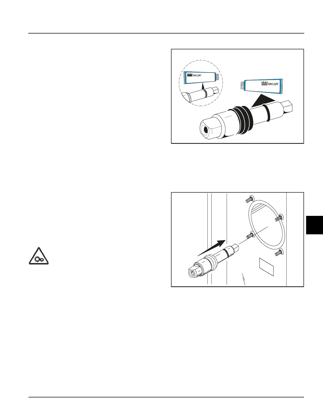
1. Slide the O-ring into the first groove on the drive
shaft. Lubricate the groove, O-ring, and shaft portion
that comes in contact with the bearing on the beater
drive shaft.
Do not lubricate the square end of the drive shaft.
Slide the seal over the shaft and groove until it snaps
into place. Fill the inside portion of the seal with 1/4
more lubricant and evenly lubricate the flat side of the
seal that fits onto the rear shell bearing.
Figure 6-1
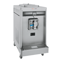
2. Insert the drive shaft into the freezing cylinder,
(square end first) and into the rear shell bearing, until
the seal fits securely over the rear shell bearing. Be
certain the drive shaft fits into the drive coupling
without binding.
Figure 6-2
3. Before installing the beater assembly, inspect the
scraper blades.
Check the scraper blades for any signs of wear or
damage. If a scraper blade is nicked or worn, replace
both blades.
4. If the blades are in good condition, place the rear
scraper blade over the rear holding pin (knife edge to
the outside). Holding the blade on the beater, turn it
over and install the front blade the same way.
11369
Apply the appropriate
Taylor approved food safe lubricant.
Apply the appropriate
Taylor approved food safe lubricant.