39
Models C708 & C716 Operating Procedures
150421
To INCREASE the flow rate, turn the adjustment
screw CLOCKWISE. To DECREASE the flow rate,
turn the adjustment screw COUNTER-
CLOCKWISE.
Step 10
Snap the design caps over the bottom of the door
spouts.
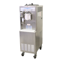
Step 11
Slide the two short drip pans into the holes in the
back panel. Slide the two long drip pans into the
holes in the side panels. (See Figure 34.)
Figure 34
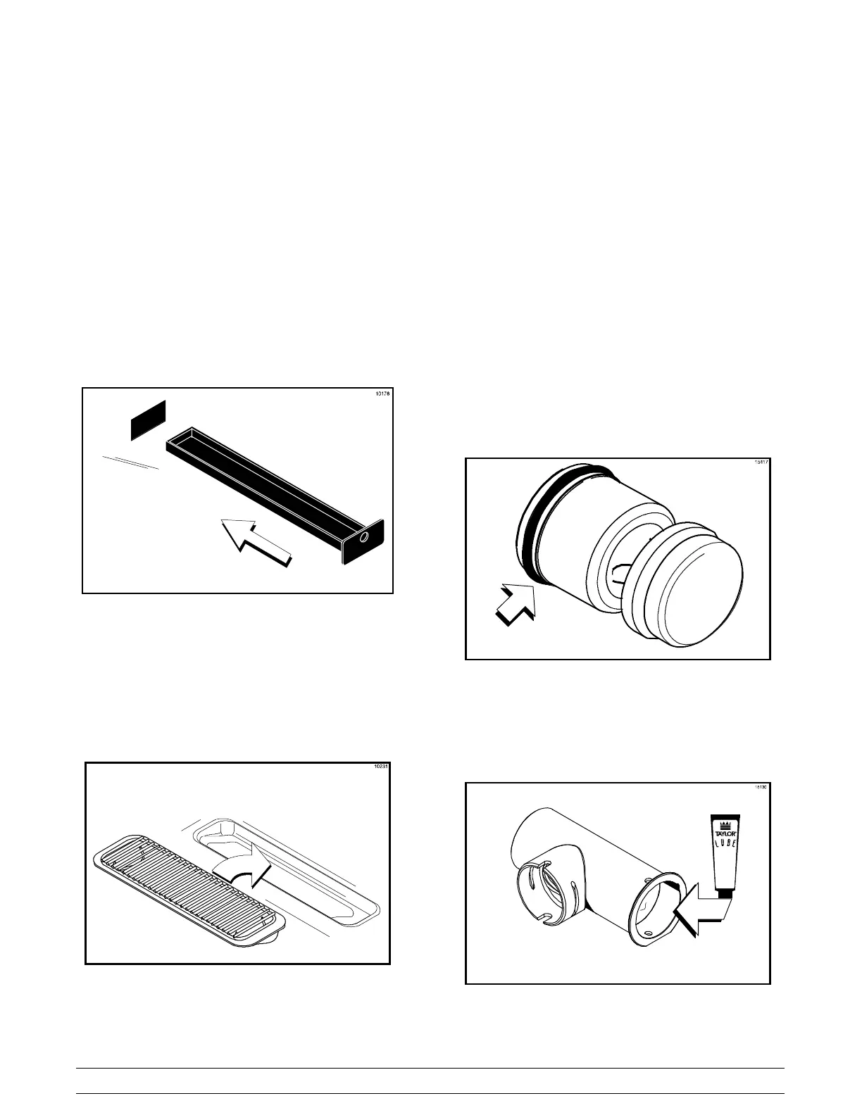
Step 12
Install the front drip tray and splash shield under the
door spouts. (See Figure 35.)
Figure 35
Mix Pump Assembly
Step 1
Inspect the rubber and plastic pump parts. The
o-rings, check rings, and gaskets must be in 100%
good condition for the pump and entire machine to
operate properly. They cannot properly serve their
intended function if nicks, cuts, o r holes in the
material are present.
Inspect the plastic pump parts for cracks, wear, and
de-lamination of plastic.
Replace any defective parts immediately and
discard the old.
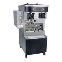
Step 2
Assemble the piston. Slide the red o-ring into the
groove of the piston. DO NOT lubricate the o-ring.
(See Figure 36.)
Figure 36
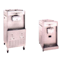
Step 3
Apply a thin layer of lubricant to the inside of the
pump cylinder at the retaining pin hole end.
(See Figure 37.)
Figure 37