and Current setting. For 5 sec. the display will show the se
ting and then it will return to show the actual Output Voltage
Front Panel Lock. Press and hold
PREV button to toggle between “Locked front pane
“Unlocked front panel”. The display will cycle b
and “UFP”. Releasing the PREV button while one of the
modes is displayed selects that mode.
Green LED, lights when PREV button is pressed
nd Current Fine/Coarse adjustment control. Ope
ates as a toggle switch. In Fine mode, the VOLTAGE and
CURRENT encoders operate with high resolution and in
Coarse mode with lower resolution (approx. 6 turns).
Green LED, lights when the unit is in Fine mode.
Red LED, blinks in case of fault detection. OVP, OTP Fol
back, Enable and AC fail detection will cause the ALARM
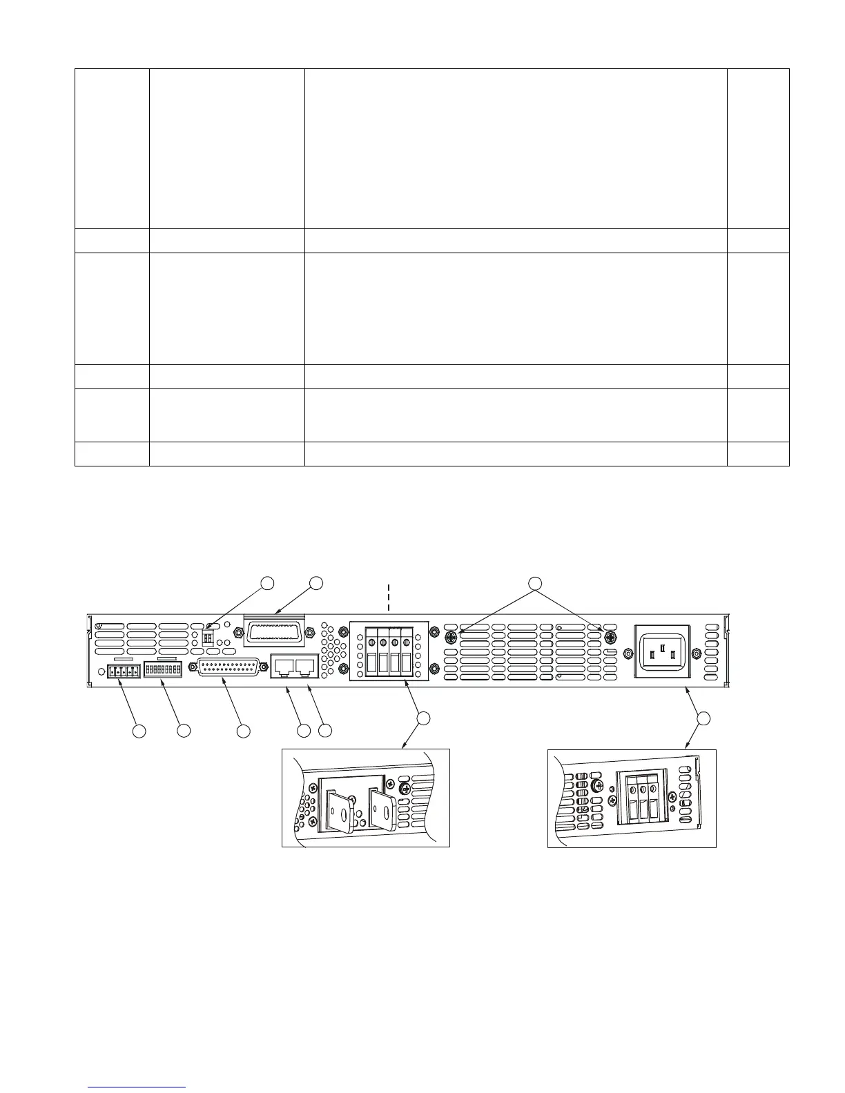
4.3 REAR PANEL CONNECTIONS AND CONTROLS
2 to review the connections and controls located on the power supply rear panel. Refer to
2 for explanations about the rear panel connections and
Fig.4-2: Rear panel connections and controls