Connecting single loads, local sensing (
10 shows recommended load and sensing connections for a single load. The local sense lines
shown are default connections at the rear panel J2 sense connector. Local sensing is suitable for a
plications where load regulation is less crit
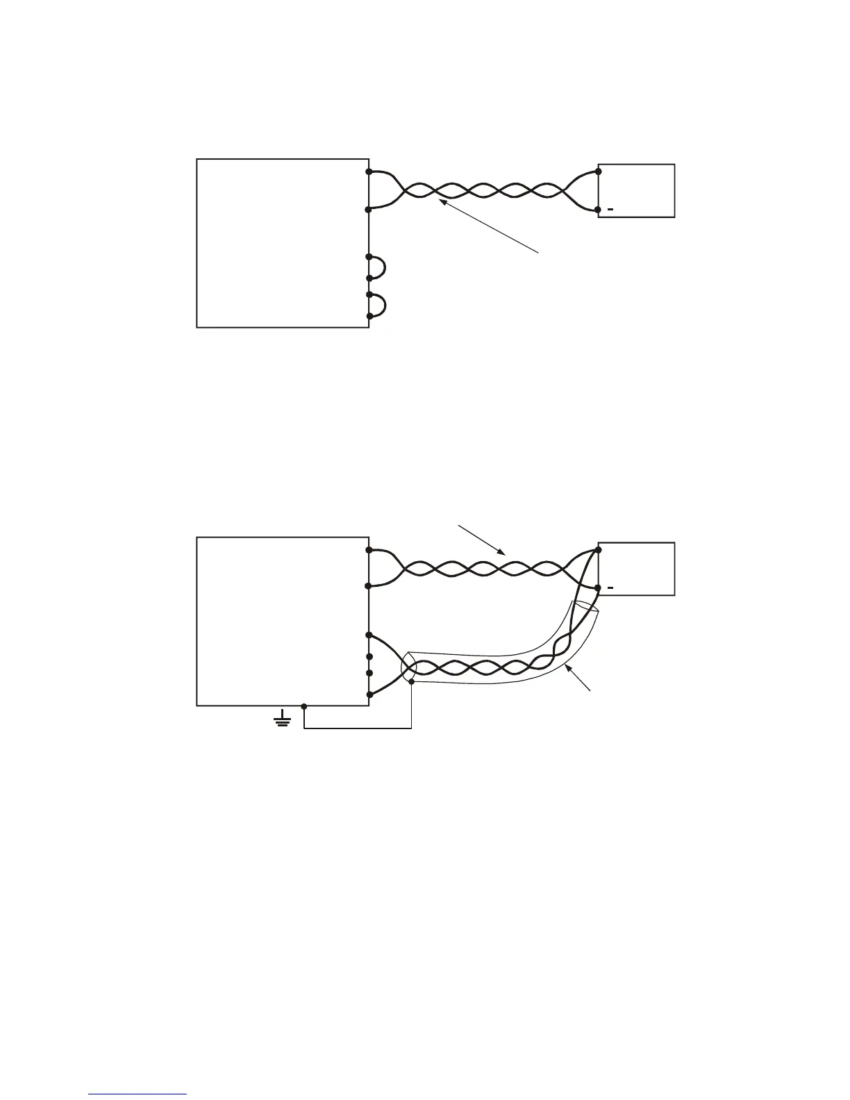
Connecting single loads, remote sensing
11 shows recommended remote sensing connection for single loads. Remote sensing is used
when, in Constant Voltage mode, the load regul
tion is important at the load terminals. Use twisted or
up. If shielded wires are used, the shield should be connected to
the ground at one point, either at the power supply chassis or the load ground. The optimal point for
the shield ground should be determined by e
ecting multiple loads, radial distribution method
12 shows multiple loads connected to one supply. Each load should be connected to the power
supply’s output terminals using separate airs of wires. It is recommended that each pair of wires will
short as possible and twisted or shielded to minimize noise pick
up and radiation. The sense
wires should be connected to the power supply output terminals or to the load with the most critical
load regulation requirement.
Fig.3-10: Single load connection, local sensing
shortest length possible.
Fig.3-11: Remote sensing, single load