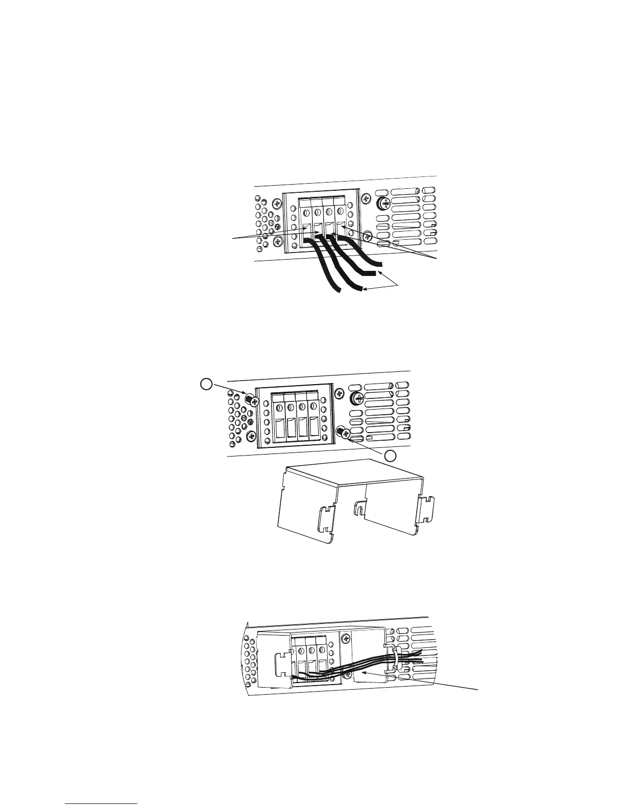
Fig.3-7: Load wires connection to the output connector
Fig.3-9: Protective shield and wires assembly
The 80V to 600V models have a four termina
l wire clamp output connector. The two left terminals are
the positive outputs and the two right terminals are the negative outputs. The connector requirements
ns below for connection of the load wires to the power supply:
Strip approx. 10mm (0.39 inches) at the end of each of the wires.
Loosen the connector terminal screws.
Insert the stripped wires into the terminal and tighten the terminal screw securely (see
Loosen the two chassis screws marked “A” halfway as shown in Fig.3
Assemble the protective shield to the chassis and tighten the two screws to fix the shield to the
8). Screws tightening torque: 4.8
Tighten the wires to one of the shield sides using typ
wrap or equivalent. Refer to Fig.3
Ensure that the wire length inside the shield is long enough to provide proper strain relief.