When the Isolated Analog Option is installed, do not apply any signals to the
isolated VPGM and IPGM (J1
. All other J1 features may
be used normally. Refer to Section 4.5 for a description of J1 features.
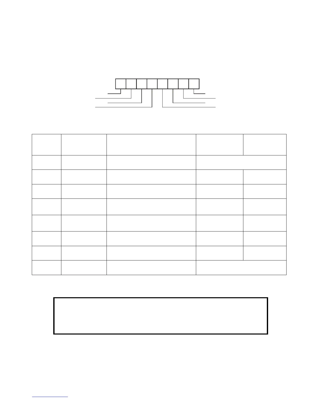
8.3 ISOLATED PROGRAMMING & MONITORING CONNECTOR
1 for detailed description of the rear panel Isolated Programming & Monitoring
connector. To provide the lowest noise perfor
mance, it is recommended to use shielded
1 for description of the Isolated Analog Programming & Monitoring connector.
Isolated programming plug P/N: MC1.5/8
1: Detailed description of Isolate
d programming & Monitoring connector
Shield, connected internally to
chassis of the power supply.
Output Voltage programming i
Output Current programming i
Ground for programming signals.
Ground for programming signals.
Output voltage monitoring output
Output current monitoring output
Shield, connected internally to
Fig.8-1: Isolated Programming & Monitoring connector