23
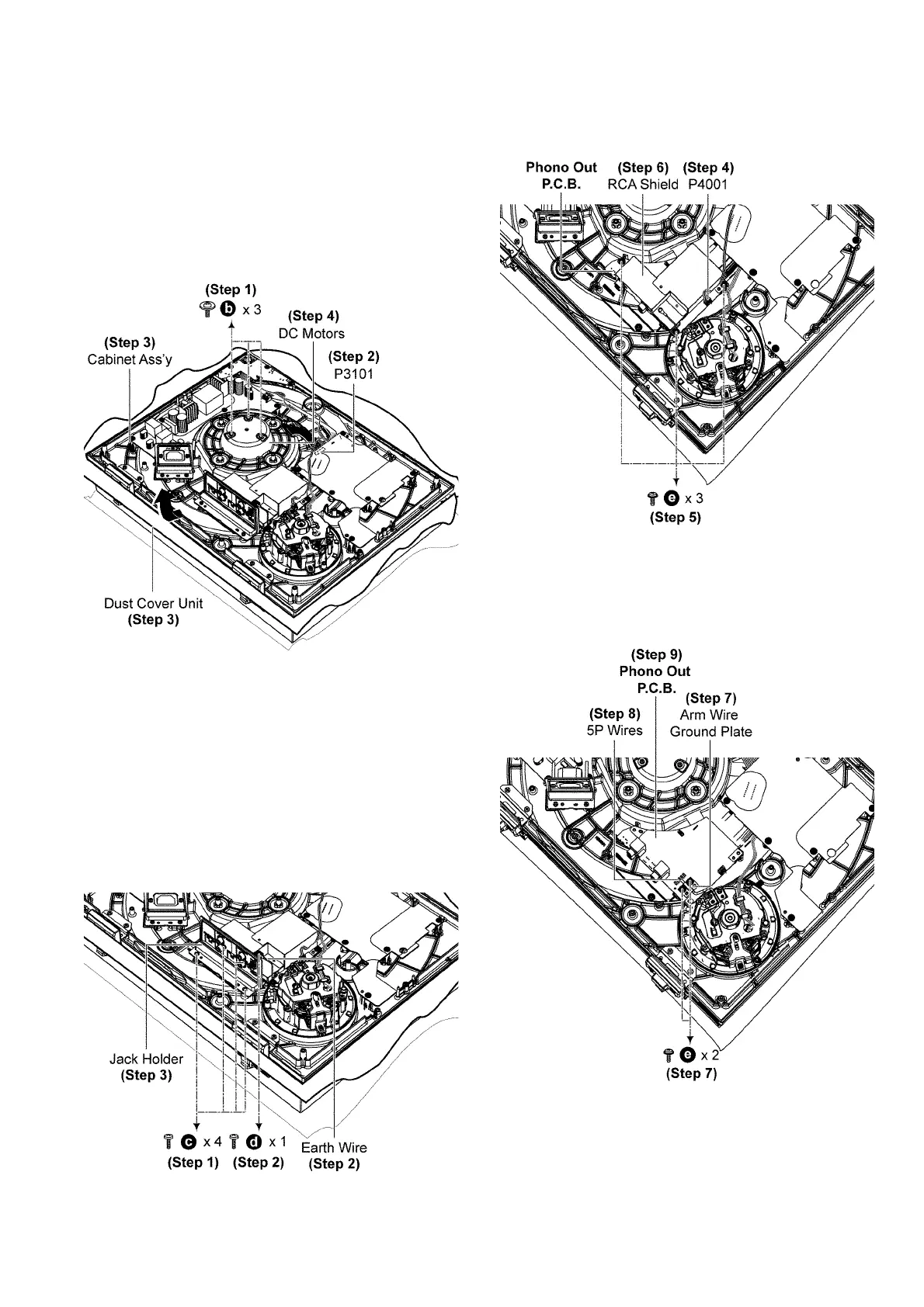
6.7. Disassembly of DC Motors
• Refer to “Disassembly of T/T Rubber Mat and Turntable
Ass’y”.
• Refer to “Disassembly of Insulator Unit”.
• Refer to “Disassembly of Bottom Chassis Ass’y”.
Step 1 Remove 3 screws.
Step 2 Detach 11P Wire at connector (P3101) on Main P.C.B..
Step 3 Separate the Cabinet Ass’y from the Dust Cover Unit.
Step 4 Remove the DC Motors.
6.8. Disassembly of Phono Out
P. C. B .
• Refer to “Disassembly of T/T Rubber Mat and Turntable
Ass’y”.
• Refer to “Disassembly of Insulator Unit”.
• Refer to “Disassembly of Bottom Chassis Ass’y”.
Step 1 Remove 4 screws.
Step 2 Remove screw and Earth Wire.
Step 3 Remove Jack Holder.
Step 4 Detach 3P Wire at connector (P4001) on Phono Out
P. C .B . .
Step 5 Remove 3 screws.
Step 6 Remove RCA Shield.
Step 7 Remove 2 screws and Arm Wire Ground Plate.
Step 8 Unsolder 5P Wires on Phono Out P.C.B..
Step 9 Remove Phono Out P.C.B..
Caution: During assembling of 5P Wires, ensure wires
properly seated on top of arm wire cushion.