5.1.1. A4M I/O Special considerations:
Table 7. Low speed pulse outputs
TBK5
Note:
on the A4M or A4B, if digital valve control is used, the digital outputs controlling the flow
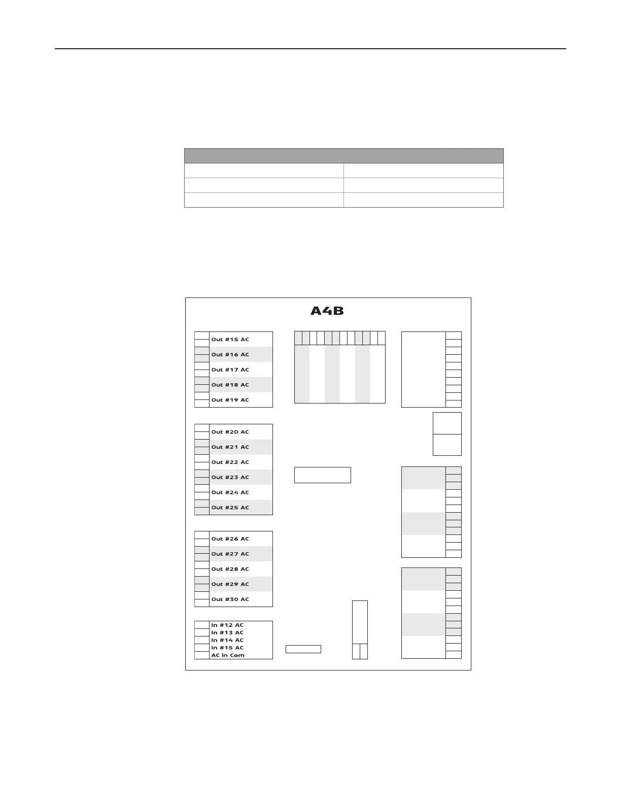
5.2. A4B module (part of the QT and SA models only)
Figure 7.
Note:
on the A4M or A4B, if digital valve control is used, the digital outputs controlling the flow
TB13
BIO In #5 1
Com #5 2
BIO Out #5 3
BIO In #6 4
Com #6 5
BIO Out #6 6
BIO In #7 7
Com #7 8
BIO Out #7 9
BIO In #8 10
Com #8 11
BIO Out #8 12
Enet
2
Enet
1
ON
S1
1 8
OFF
TB14
HS PRV +1
HS PRV -2
NC 3
NC 4
NC 5
NC 6
NC 7
NC 8
Gnd 9
Gnd 10
F1
TB10
1
2
3
4
5
6
7
8
9
10
TB9
1
2
3
4
5
6
7
8
9
10
11
12
TB11
1
2
3
4
5
TB12
BIO In #1 1
Com #1 2
BIO Out #1 3
BIO In #2 4
Com #2 5
BIO Out #2 6
BIO In #3 7
Com #3 8
BIO Out #3 9
BIO In #4 10
Com #4 11
BIO Out #4 12
TB8
1
2
3
4
5
6
7
8
9
10
1+
Pulse In #9
2-
3+
Pulse In #10
4-
5+
Pulse In #11
6-
7+
Pulse In #12
8-
9+
Pulse In #13
10 -
11 +
Pulse In #14
12 -
PT1
Ground 2
+24 VDC 1
TB2