GLIDEX 600 XTPRO: Service & Maintenance Manual - rev. 1.1
Page 6.8
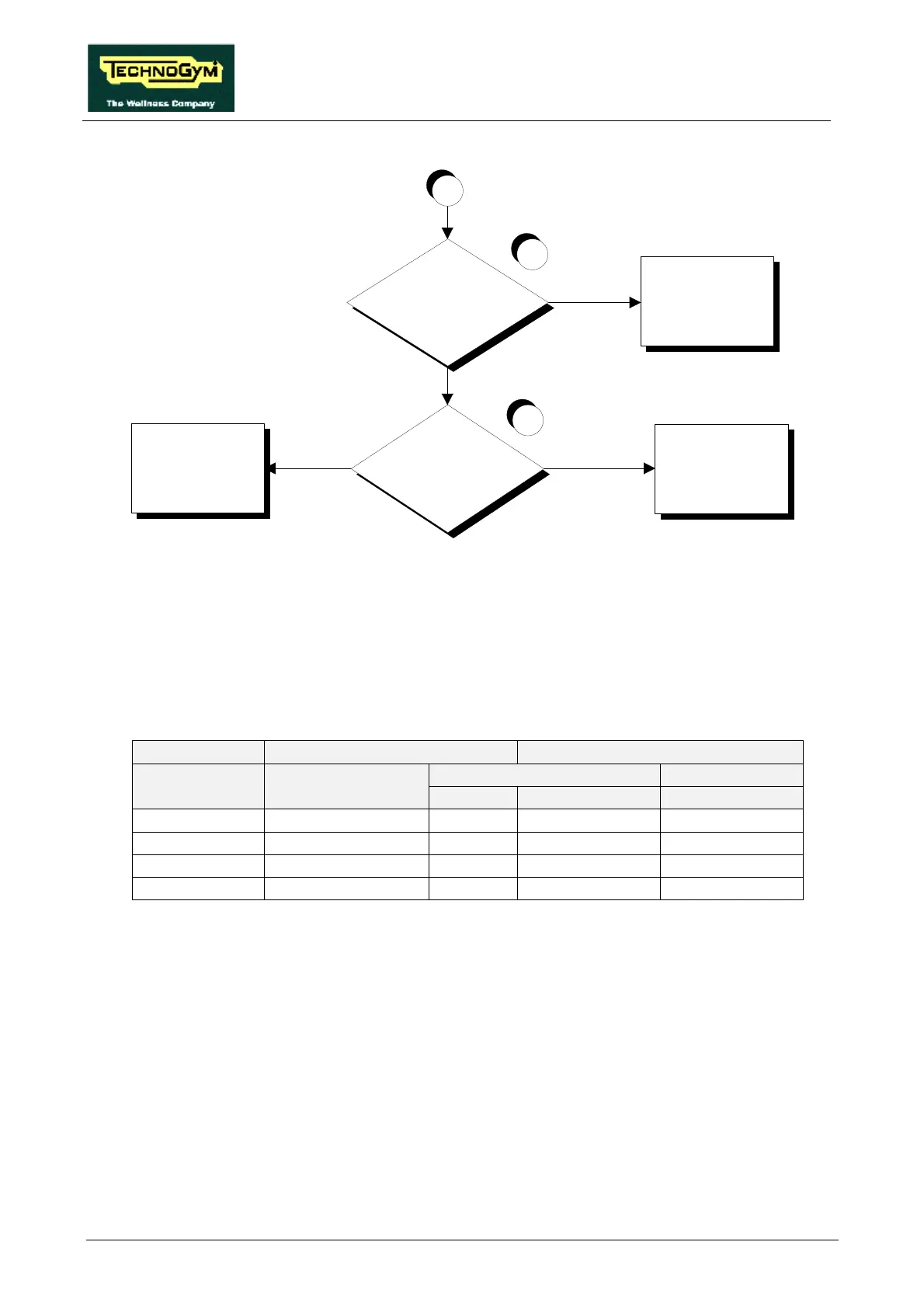
Does the CPU board send
the correct control signal to
the alternator interface
board?
Replace the cable
between the panel
connector and the
alternator interface board
Replace the alternator
interface board
YES
YES
NO
NO
5
6
Replace the cable
between the CPU board
and the panel connector
Is the control signal at the
panel connector correct?
A
Follow the procedure step by step to correctly diagnose the problem. Take particular care with the
checks highlighted by circled numbers, which are described in detail below:
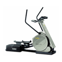
(1) Place the tester probes between the orange (positive) and black (negative) cables on the
alternator. Select the “Quick Start” function on the display and start exercising on the
machine. When the level of difficulty is varied, maintaining the speed indicated in Table
6.3-1, the excitation voltage should vary as shown in the same table:
SPM = 100 Excitation (Vdc) PFM signal (Hz)
Alternator interface board CPU board Effort level Alternator
4-5/CN2 6-3/CN1 6-3/CN1
1 1.1 1.1 55 55
3 2.2 2.2 140 140
6 3.8 3.8 267 267
9 6.0 6.0 385 385
Table 6.3-1
The voltages and frequencies quoted above are nominal values.
(2) As for step (2) but with the tester between pins 4 and 5 of connector CN2 on the alternator
interface board.
(3) Disconnect all the cables from the 2 power resistor terminals. Place the tester probes on the 2
terminals and measure the value of the resistance. The correct value for the power resistor is
approximately 0.5 Ohm.