GLIDEX 600 XTPRO: Service & Maintenance Manual - rev. 1.1
Page 7.7
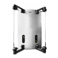
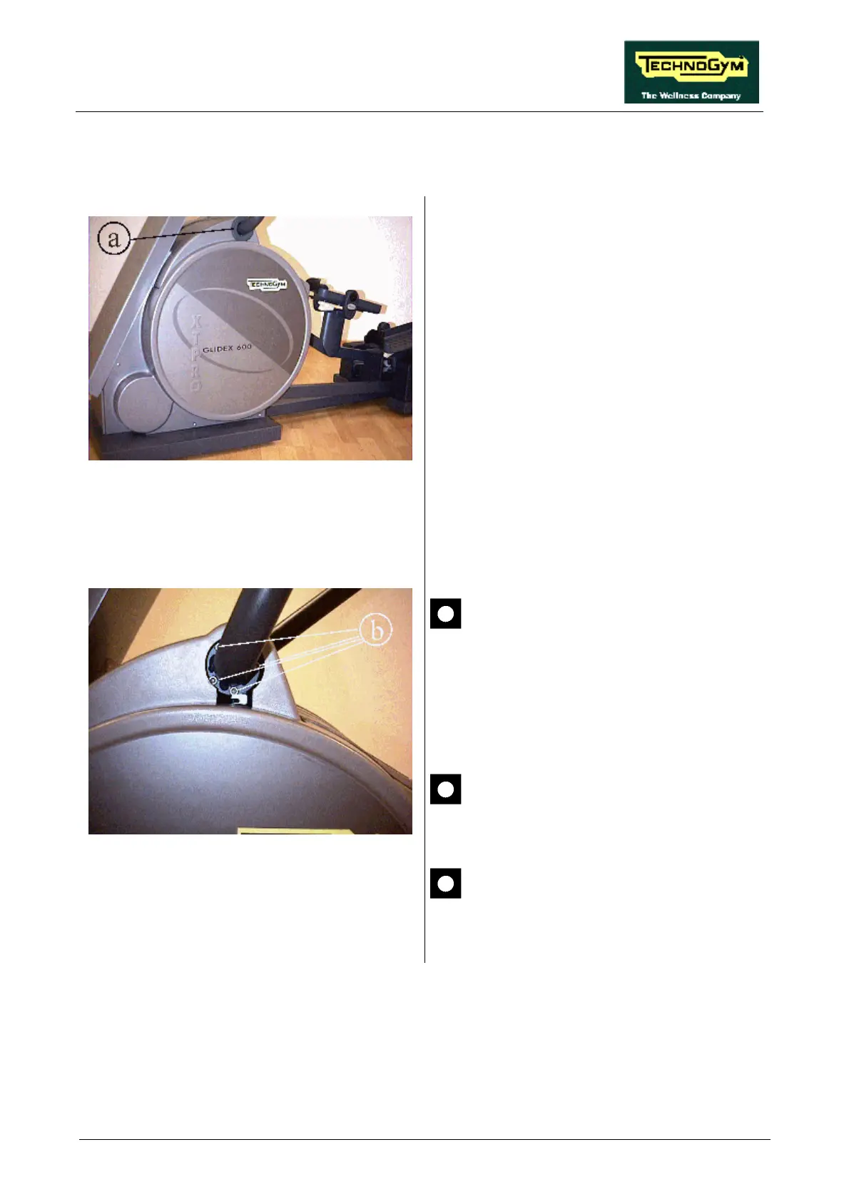
7.6. DISASSEMBLING THE LEVERS
Figure 7.6-1
1. Turn off the machine and unplug the mains
lead from the wall outlet.
2. On each side, remove the rubber guard a.
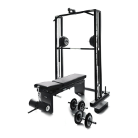
Figure 7.6-2
On each side:
3. Back off the 4 screws b using a 6-mm hex T
wrench.
Support the lever before backing off the
last screw.
4. Remove the lever.
To reassemble the LEVERS, carry out the above
steps in reverse order.
Clean and thoroughly degrease the
contact surface between the lever and
frame.
On reassembly, the screws c must be
locked down using a torque wrench
setting of 40 Nm (29.5 ft.lbs).