GLIDEX 600 XTPRO: Service & Maintenance Manual - rev. 1.1
Page 6.11
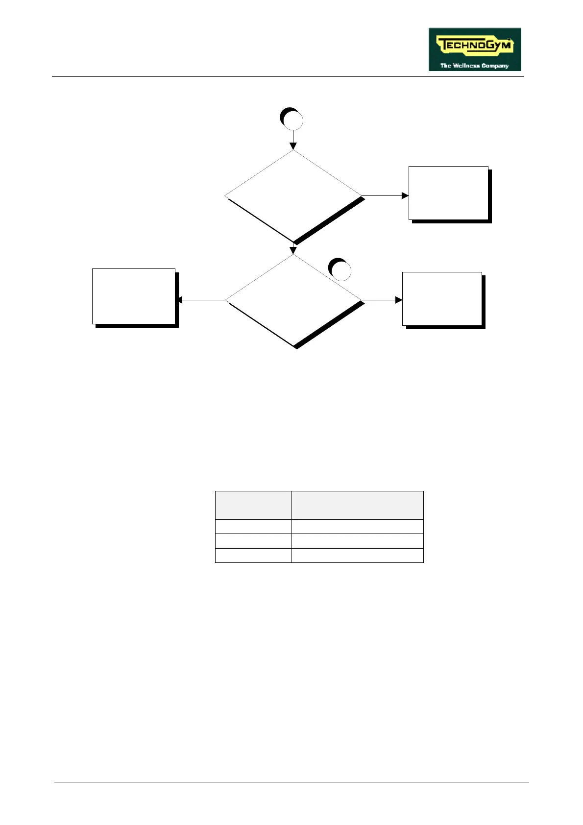
Replace cable which
connects the CPU board
to panel connector
CN11
Replace the display CPU
board
NO
SI
5
Is the SPM signal on connector
CN1 of the CPU board correct?
A
SI
Is the SPM signal on panel
connector CN11 correct?
Replace cable which
connects the alternator
interface board to panel
connector CN11
NO
Follow the procedure step by step to correctly diagnose the problem. Take particular care with the
checks highlighted by circled numbers, which are described in detail below:
(1) Check whether the black and violet wires, which connect the alternator to pins 1 and 5 of CN2
on the alternator interface board, are correctly connected.
(2) Place the probes of an oscilloscope between the violet wire and the alternator ground. When
the speed is varied, the waveform frequency should vary as shown in the table below:
SPM FREQUENCY
(Hz)
90 95
120 127
150 159
(3) As for step (2) but with the oscilloscope probes between pins 1 and 5 of connector CN2 on the
alternator interface board.
(4) As for step (2) but with the oscilloscope probes between pins 5 and 3 of connector CN1 on the
alternator interface board.
(5) As for step (2) but with the oscilloscope probes between pins 5 and 3 of connector CN1 on the
display CPU board.