© Technosoft 2011 43
IDMx40 Technical Reference
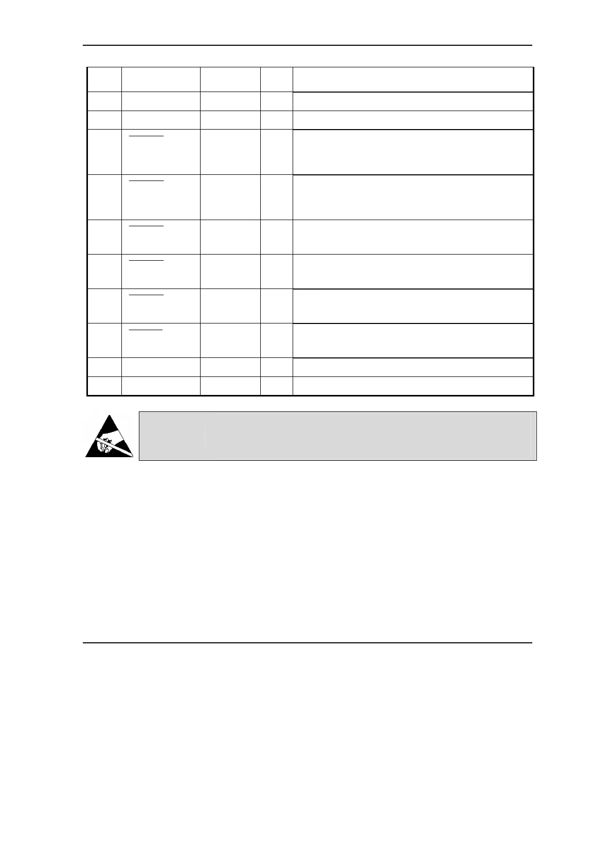
17 -Tach I
position or speed feedback (from a tachometer).
Internally filtered (3.4 KHz).
18 GND - O
Ground of the +5 V
DC
.power supply output
19 24 VPLC - I
24 V power supply (+) for all opto-isolated I/O
20
OUT#12 /ER
OUT#12 /
ERROR
O
24 V compatible output. Opto-isolated
TML instruction ROUT#12 force this pin to +24 V and
set light to the red LED
21
OUT#25
/RD
OUT#25 /
READY
O
24 V compatible output. Opto-isolated
TML instruction ROUT#25 force this pin to +24 V and
set light to the green LED
22
OUT#28
OUT#28 O
24 V compatible output. Opto-isolated
TML instruction ROUT#28 force this pin to +24 V
23
OUT#29
OUT#29 O
24 V compatible output. Opto-isolated
TML instruction ROUT#29 force this pin to +24 V
24
OUT#30
OUT#30 O
24 V compatible output. Opto-isolated
TML instruction ROUT#30 force this pin to +24 V
25
OUT#31
OUT#31 O
24 V compatible output. Opto-isolated
TML instruction ROUT#31 force this pin to +24 V
26 0VPLC - I
24 V power supply (-) for all opto-isolated I/O
case SHIELD - - Shield
CAUTION!
THE I/O CONNECTOR SIGNALS ARE ELECTRO-
STATICALLY SENSITIVE AND SHALL BE HANDLED ONLY
IN AN ESD PROTECTED ENVIRONMENT.
Remarks:
3. The 24V opto-isolated I/O signals are referenced to the isolated ground 0VPLC, which
shall be common to all the devices sharing these signals.
4. The 24V opto-isolated inputs have a typical threshold of 8 Volts, therefore will not accept
TTL levels.
5. The isolated 24VPLC supply is required only for operation of the outputs. Hence, if your
application uses only opto-isolated inputs, the 24VPLC supply connection is not
necessary.
6. The inputs IN#37/D and IN#38/P accept both TTL (5V) and 24V signals and are opto-
isolated. These inputs are referenced to the drive logic ground GND