© Technosoft 2011 42
IDMx40 Technical Reference
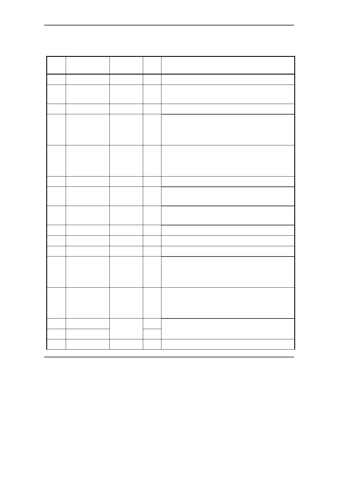
3.2.5. Analog & Digital I/O – J9 Connector
Pin Name on the
Drive cover
TML
name
Typ
e
Function / Alternate function / Comments
1 24 VPLC - I
24 V power supply (+) terminal for all opto-isolated I/O
2 IN#16/EN IN#16 /
ENABLE
I
24 V compatible input. Opto-isolated
Connect to +24 V to disable the PWM outputs
3 IN#36 IN#36 I
24 V compatible input. Opto-isolated.
4 IN#37/D IN#37 /
DIR
I
24 V compatible input. Opto-isolated. Shared with pin
12 (IN#37/D5V)
Can be used as DIRECTION input in Pulse & Direction
motion mode
5 IN#38/P IN#38 /
PULSE
I
24 V compatible input. Opto-isolated. Shared with pin
13 (IN#38/P5V)
Can be used as PULSE input in Pulse & Direction
motion mode
6 IN#39 IN#39 I
24 V compatible input. Opto-isolated
7 IN#2/LSP IN#2 /
LSP
I
24 V compatible input. Opto-isolated
Positive limit switch
8 IN#24/LSN IN#24 /
LSN
I
24 V compatible input. Opto-isolated
Negative limit switch
9 0VPLC - I
24 V power supply (-) terminal for all opto-isolated I/O
10 +V
LOG
- O + V
LOG
. Logic supply voltage (as applied on J2, pin 7)
11 RESET - I
RESET pin – connect to +24 V for reset the board
12 IN#37/D5 V IN#37 /
DIR
I
5 V compatible input. Opto-isolated. Shared with pin 4
(IN#37/D)
Can be used as DIRECTION input in Pulse & Direction
motion mode
13 IN#38/P5 V IN#38 /
PULSE
I
5 V compatible input. Opto-isolated. Shared with pin 5
(IN#38/P)
Can be used as PULSE input in Pulse & Direction
motion mode
14 +Ref I
15 -Ref
AD5
I
+/-10 V differential analog input. May be used as analog
position, speed or torque reference
16 +Tach AD2 I
+/-10 V differential analog input. May be used as analog