© Technosoft 2011 53
IDMx40 Technical Reference
3.2.8. Connectors Type and Mating Connectors
Connector Function Mating connector
J2 Motor & supply Phoenix Contact MC 1.5/8-STF-3.5
1
J4 Serial generic 9-pin Sub-D male
J10 & J11 CAN generic RJ11-4/4 phone plug
J13 Feedback generic 15-pin High Density Sub-D male
J9 Analog & 24 V digital I/O generic 26-pin High Density Sub-D male
1
. The mating connector accepts wires of 0.14 … 1.5 mm
2
(AWG28 … AWG16)
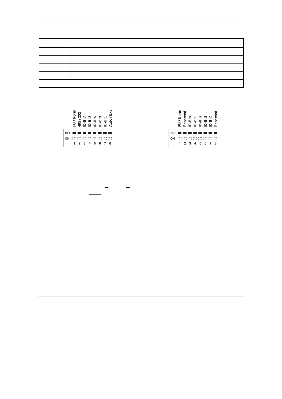
3.3. DIP-Switch Settings
Figure 3.32. SW1 – DIP Switch for CAN
executions
Figure 3.33. SW1 – DIP Switch for CANopen
executions
• Position 1: FU / Norm
ON: Enable F
irmware Update
OFF: Norm
al operation
• Position 2: 485/232 (CAN executions)
ON: IDMx40 drive communicates in RS-485 mode
OFF: IDMx40 drive communicates in RS-232 mode
• Positions 3 … 7: ID-Bitx.
Axis ID switches The drive axis/address number is set according with Table 3.1
• Position 8: Auto / Ext (CAN executions)
ON: Sets the drive in AUTORUN mode (only with TMLCAN protocol). After power-on,
the drive automatically executes a TML program from its internal E
2
ROM.
OFF: Sets the drive in External (slave) mode. After power-on, the drive waits for
commands from an external device. With CANopen protocol, the drive is always in
external mode independently of the switch position
Remark: All switches are sampled at power-up, and the drive is configured accordingly