© Technosoft 2011 33
IDMx40 Technical Reference
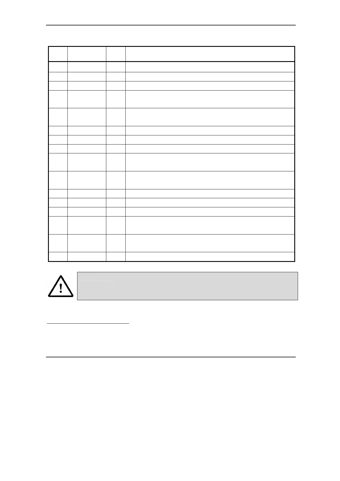
3.2.4. Feedback – J13A Connector
Pin
Name on the
Drive cover
Type Function / Comments
1 A1+ I
Positive A for differential encoder or A for single-ended encoder
23
*)
2 B1+ I
Positive B for differential encoder or B for single-ended encoder
1
*)
3 +5 V
DC
O
+5 V
DC
Supply (generated internally)
4 H3/A2/CK+ I
Positive Hall 3 for differential Hall or Hall 3 for single-ended Hall
2
*)
Second encoder positive A for differential encoder or A for single-ended encoder
5 H1/B2/DT+ I
Positive Hall 1 for differential Hall or Hall 1 for single-ended Hall
2
*)
Second encoder positive B for differential encoder or B for single-ended encoder
6 Therm I
Analog input from motor thermal sensor
7 Z1+ I
Positive Z for differential encoder or Z for single-ended encoder
1
*)
8 Z1- I
Negative Z for differential encoder
9 H2/Z2+ I
Positive Hall 2 for differential Hall or Hall 2 for single-ended Hall
2
*)
Second encoder positive Z for differential encoder or Z for single-ended encoder
10 H2/Z2- I
Negative Hall 2 for differential Hall
Second encoder: negative Z for differential encoder
11 A1- I
Negative A for differential encoder
12 B1- I
Negative B for differential encoder
13 GND -
Ground of the encoder supply
14 H3/A2/CK- I
Negative Hall 3 for differential Hall
Second encoder negative A for differential encoder
15 H1/B2/DT- I
Negative Hall 1 for differential Hall
Second encoder negative B for differential encoder
case SHIELD -
Shield
CAUTION!
CHECK CURRENT CONSUMPTION FROM +5VDC SUPPLY!
BYPASSING THE MAXIMUM ALLOWED CURRENT MIGHT
LEAD TO DRIVE MALFUNCTION
23
*) In application configurations without any encoder feedback, this input may be used as a general-purpose input.
2
*) In application configurations without any Hall or second encoder feedback, this input may be used as a general-purpose
input.