25
1.11.1 Brake System
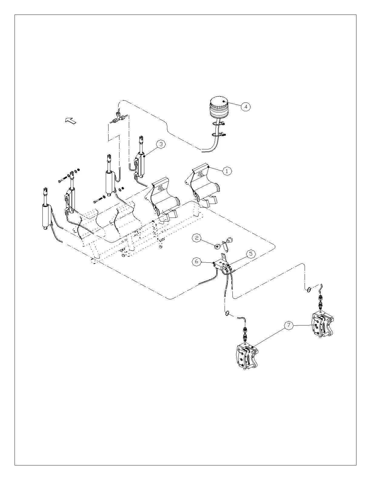
Figure 7-2 shows the brake system schematic diagram.
The left and right wheel brakes are independent systems. The system has a reservoir (4) on the co-pilot’s brake pedals (1).
The reservoir is directly connected to the brake master cylinders (3). Two flexible hoses connect the master cylinders on the
co-pilot’s brake pedals to the master cylinders on the pilot’s brake pedals.
The parking brake valve (6) is mounted on the floor of the fuselage, below the seats and it’s activated by lever (2).
Each main wheel has a brake disc (7).
Fig. 1-7 Brake System