27
2-1-5 TB Terminal
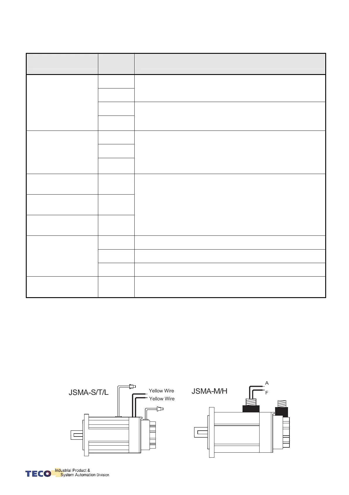
2-1-6 Wiring for Mechanical Brake
Uninstall BRAKE:
JSMA-S/L/T series: Use Red wire and yellow wire connecting to DC +24V voltage(No polarity)
JSMA-M/H series: BK outputs from A & F of Motor Power Joint, servo motor can operate
normally after uninstalling.
Encoder
Brake
Encoder
Brake
Name
Terminal
Sign
Detail
Control circuit power input
terminal
r
200V
Connecting to external AC Power.
Single Phase 200~230VAC +10 ~ -15% 50/60Hz ±5%
s
24V
400V
Connecting to external DC Power.
Single Phase 24VDC ±10%.
0V
Main circuit power input
terminal
R
200V
Connecting to external AC Power.
Single / 3 Phase 200~230VAC +10 ~ -15% 50/60Hz ±5%
400V
Connecting to external AC Power.
Three Phase 380~480VAC ±10% 50/60Hz ±5%
S
T
External regeneration
resistance terminal
P
Please refer to Cn012 to see resistance value, when using external
regeneration resistance. After installing regeneration resistance, set the
resistance power in Cn012.
*If no using external regeneration resistance, PC-P1 need be close, P
doesn’t be connected.
*When using external regeneration, equip regeneration resistance
between PC-P, do not connect P1 terminal.
Regeneration terminal
common point
PC
Internal regeneration
resistance terminal
P1
Motor-power output
terminal
U
Motor terminal wire is red
V
Motor terminal wire is white
W
Motor terminal wire is black
Motor-case grounding
terminal
FG
Motor terminal wire is green or yellow-green.
 Loading...

