38
Chapter 3 Panel Operator / Digital Operator
3-1 Panel Operator on the Drives
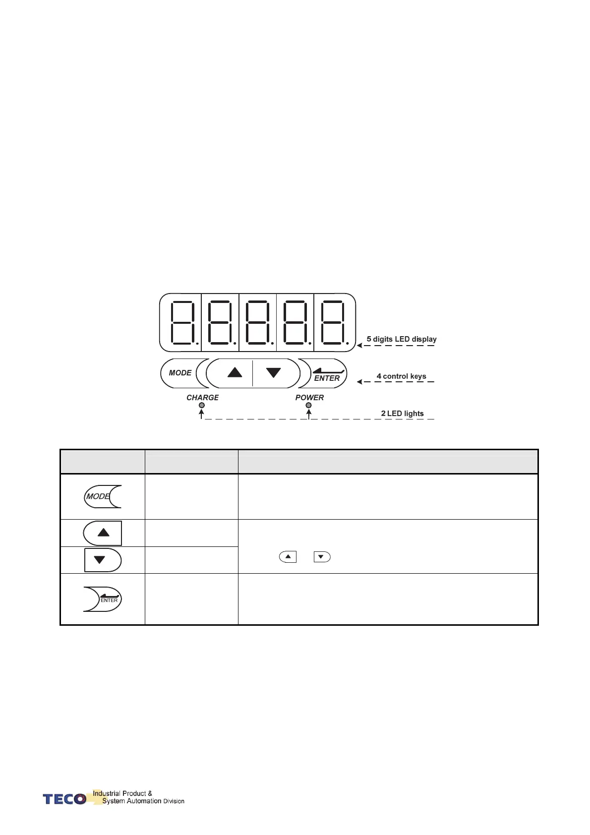
The operator keypad & display contains a 5 digit 7 segment display, 4 control keys and two status
LED displays.
Power status LED (Green) is lit when the power is applied to the unit.
Charge LED (Red) Indicate the capacitor‘s charge status of main circuit. Power on to light up
Charge LED and gradual dark when internal power capacitors are discharged complete.
Do NOT wire or assemble to the servo drive before Charge LED is off.
Key
Name Function Keys Description
MODE/SET
1. To select a basic mode, such as the status display mode, utility
function mode, parameter setting mode, or monitor mode.
2. Returning back to parameter selection from data-setting screen.
INCREMENT
1. Parameter Selection.
2. To increase the set value.
3. Press
and at the same time to clear ALARM.
DECREMENT
DATA SETTING
&
DATA ENTER
1. To confirm data and parameter item.
2. To shift to the next digit on the left.
3. To enter the data setting (press 2 sec.)

 Loading...
