22
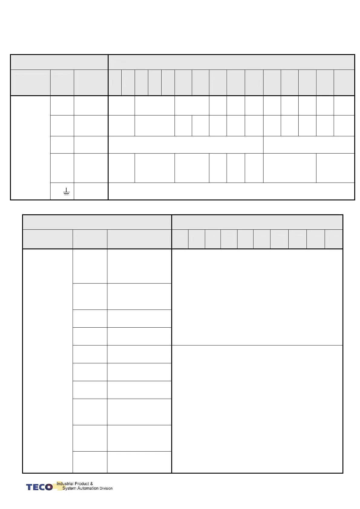
2-1-3 Specifications of Wiring
Connection Terminal
Servo Drives and Wire Specifications mm² (AWG)
Connection
Terminal
Mark
(Sign)
Name of
Connect
Terminal
10 15 20 30 50 75 100 150 200 300 25B 35B 50B 75B 100B
Terminal
R、S、
T
Main Power
Terminal
1.25
(16)
2.0
(14)
3.5
(12)
5.5
(10)
8.0
(8)
22.0
(4)
2.0
(14)
2.0
(14)
3.5
(12)
3.5
(12)
3.5
(12)
U、V、
W
Motor
Terminal
1.25
(16)
2.0
(14)
3.5
(12)
5.5
(10)
8.0
(8)
14.0
(6)
22.0
(4)
2.0
(14)
2.0
(14)
3.5
(12)
3.5
(12)
5.5
(10)
r、s
Power-Contro
Terminal
1.25
(16)
0.2
(24)
P、Pc
External
regeneration
resistance
terminal
1.25
(16)
2.0
(14)
3.5
(12)
5.5
(10)
8.0
(8)
22.0
(4)
1.25
(16)
14.0
(6)
FG
Ground
Over 2.0(14)
Connection Terminal Servo Drives and Wire Specifications
Connection
Terminal
Position
Number
Position Name
10 15 20 30 50 75 100 150 200 300
CN1
Joint Control
Signal
26,27
Speed Command /
Limit ; Torque
Command / Limit
(SIC/ TIC)
0.2mm ² or 0.3mm ² -> Twisted-pair-cable connecting to the
Analog Grounding wire (including shield cable)
30,31
Analog Monitor
Output (MON 1 &
MON 2)
33,34
Power Output +15V &
-15V
28,29,32
Analog Ground
Terminal (AG)
1~12
General Analog Input
(DI)
0.2mm ² or 0.3mm ² -> Twisted-pair-cable connecting to the
I/O Grounding wire (including shield cable)
18~25
General Analog
Output (DO)
43
Home Signal Output
(ZO)
47,44
DI PW Command
Point / DO Common
(DICOM / DOCOM)
45,46,
48
24V Power &
I/O Ground (IP24 /
IG24)
49
Absolute Encoder
Power Supply (BAT+)
 Loading...

