51
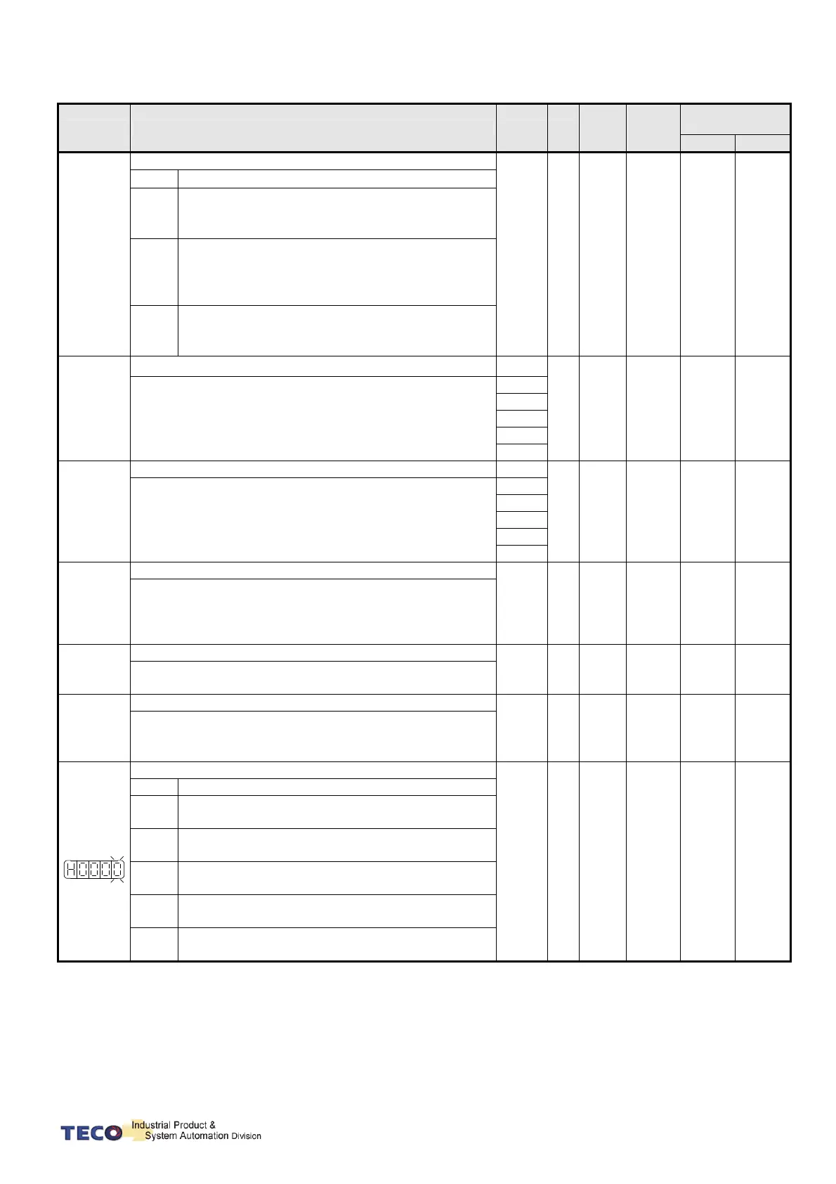
Parameter Name & Function Default Unit
Setting
Range
Control
Mode
Communication
Address
RS232 RS485
★
Cn009
CW/CCW drive inhibit mode
0 X
0
│
2
ALL 517H 0009H
Setting Explanation
0
When torque limit reached the setting value of
(Cn010,Cn011), servo motor deceleration to stop
in the zero clamp condition.
1
Deceleration by using dynamic brake to stop then
hold in dynamic brake status. Cn009 setting has
priority over Cn008 setting, it require re-cycling
power to take effect after setting changed.
2
Once max torque limit (± 300% ) is detected then
deceleration to stop, zero clamp is applied when
stop.
Cn010
CCW Torque command Limit.
300
%
0
│
300
ALL 518H 000AH
Ex: For a torque limit in CCW direction which is twice the
rated torque , set Cn10=200.
P.S.)default would depends on Cn030
260
250
240
220
200
Cn011
CW Torque command Limit.
-300
%
-300
│
0
ALL 519H 000BH
Ex: For a torque limit in CW direction which is twice the
rated torque , set Cn11=-200.
P.S.)default would depends on Cn030
-260
-250
-240
-220
-200
Cn012
Power setting for External Regeneration Resistor
0
/60
/150
W
0
│
10000
ALL 51AH 000CH
Refer to section 5-6-7 to choose external Regen resister
and set its power specification in Watts of Cn012.
P.S.)This default value will change depend on servo model
P.S.)Different series of servo has different default
Cn013
Frequency of resonance Filter ( Notch Filter).
0 Hz
0
│
1000
Pi
Pe
S
C40H 000DH
Enter the vibration frequency in Cn013, to eliminate system
mechanical vibration.
Cn014
Band Width of the Resonance Filter.
7 X
1
│
100
Pi
Pe
S
C41H 000EH
Adjusting the band width of the frequency, lower the band
width value in Cn014, restrain frequency Band width will be
wider.
Cn015.0
PI/P control switch mode.
4 X
0
│
4
Pi
Pe
S
C07H 000FH
Setting Explanation
0
Switch from PI to P if the torque command is larger
than Cn016.
1
Switch from PI to P if the speed command is larger
than Cn017.
2
Switch from PI to P if the acceleration rate is larger
than Cn018.
3
Switch from PI to P if the position error is larger
than Cn019.
4
Switch from PI to P be the input contact PCNT.
Set one of the multi function terminals to option 03.

 Loading...
