16
2-1-4 Motor Terminal Layout
A Table of Motor Terminal Wiring
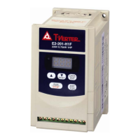
(1) General Joint:
Terminal Symbol Cable Color Signal
1 Red U
2 White V
3 Black W
4 Green FG
Fine red DC +24V
Brake control wire
Fine yellow 0V
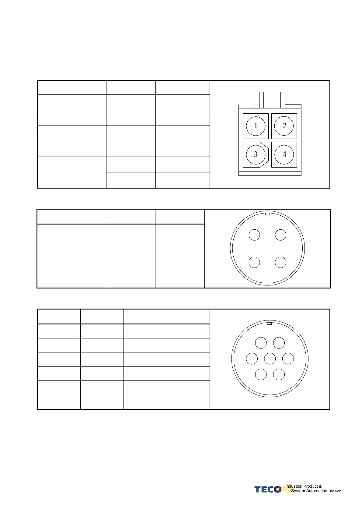
(2)Military Specifications Joint (Without Mechanical Brake):
Terminal Symbol Cable Color Signal
A Red U
B White V
C Black W
D Green FG
A
B
D
C
(3)Military Specifications Joint( With Mechanical Brake):
Terminal
Symbol
Cable Color Signal
B Red U
G White V
E Black W
C Green FG
A Fine red DC +24V (Brake control)
F Fine yellow 0V (Brake control)
A
B
DC
E
F
G