Section
7-314
Service
DIAGRAMS AND CIRCUIT BOARD ILLUSTRATIONS
Symbols and Reference Designators
Electrical components shown on the diagrams are in the following units unless noted otherwise:
Capacitors
=
Values one or greater are in picofarads (pF).
Values less than one are in microfarads (pF).
Resistors
=
Ohms
(a).
Symbols used on the diagrams are based on ANSl Standard
Y32.2-1975.
Logic symbology is based on ANSl
Y32.14-1973
in terms of positive logic.
Logic symbols depict the logic
function performed and may differ from the manufacturer's data.
The following prefix letters are used as reference designators to identify components or assemblies on the diagrams.
Assembly, separable or repairable
(circuit board, etc.)
Attenuator, fixed or variable
Motor
Battery
Capacitor, fixed or variable
Circuit breaker
Diode, signal or rectifier
Delay line
Indicating device (lamp)
Spark Gap
Fuse
Filter
Heat dissipating device (heat sink,
heat radiator, etc.)
Heater
Hybrid circuit
Connector, stationary portion
Relay
Inductor, fixed or variable
Meter
Connector, movable portion
Transistor or silicon-controlled
rectifier
Resistor, fixed or variable
Thermistor
Switch or contactor
Transformer
Thermocouple
Test point
Assembly, inseparable or non-repairable
(integrated circuit,
etc.)
Electron tube
Voltage regulator (zener diode, etc.)
Wirestrap or cable
Crystal
Phase shifter
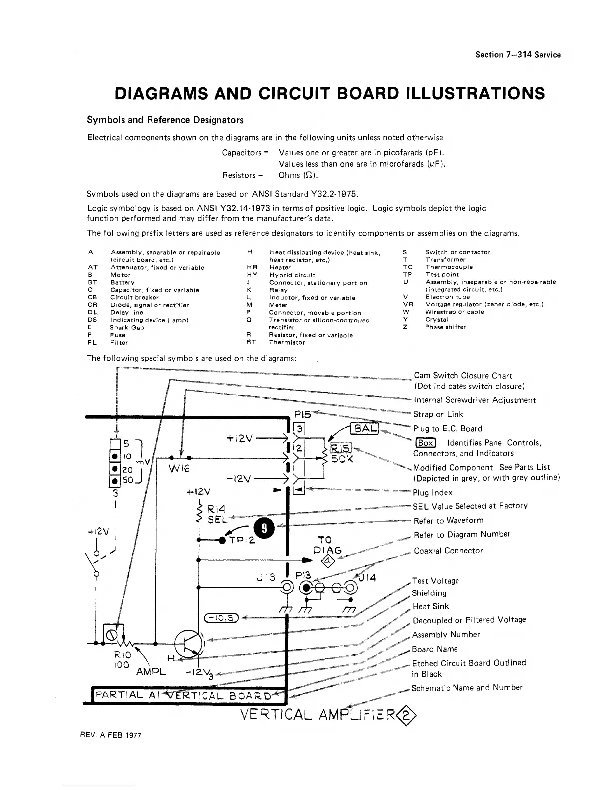
The following special symbols are used on the diagrams:
(Depicted in grey, or with grey
_
_
I
--
---
--SEL Value Selected
at
Factory
Refer to Waveform
Refer to Diagram Number
Coaxial Connector
outline)
Heat Sink
Decoupled or Filtered Voltage
#Re.
"
/Assembly Number
'O
A
\
Etched Circuit Board Outlined
Schematic Name and Number
REV.
A
FEB
1977