Theory of Operation-314 Service
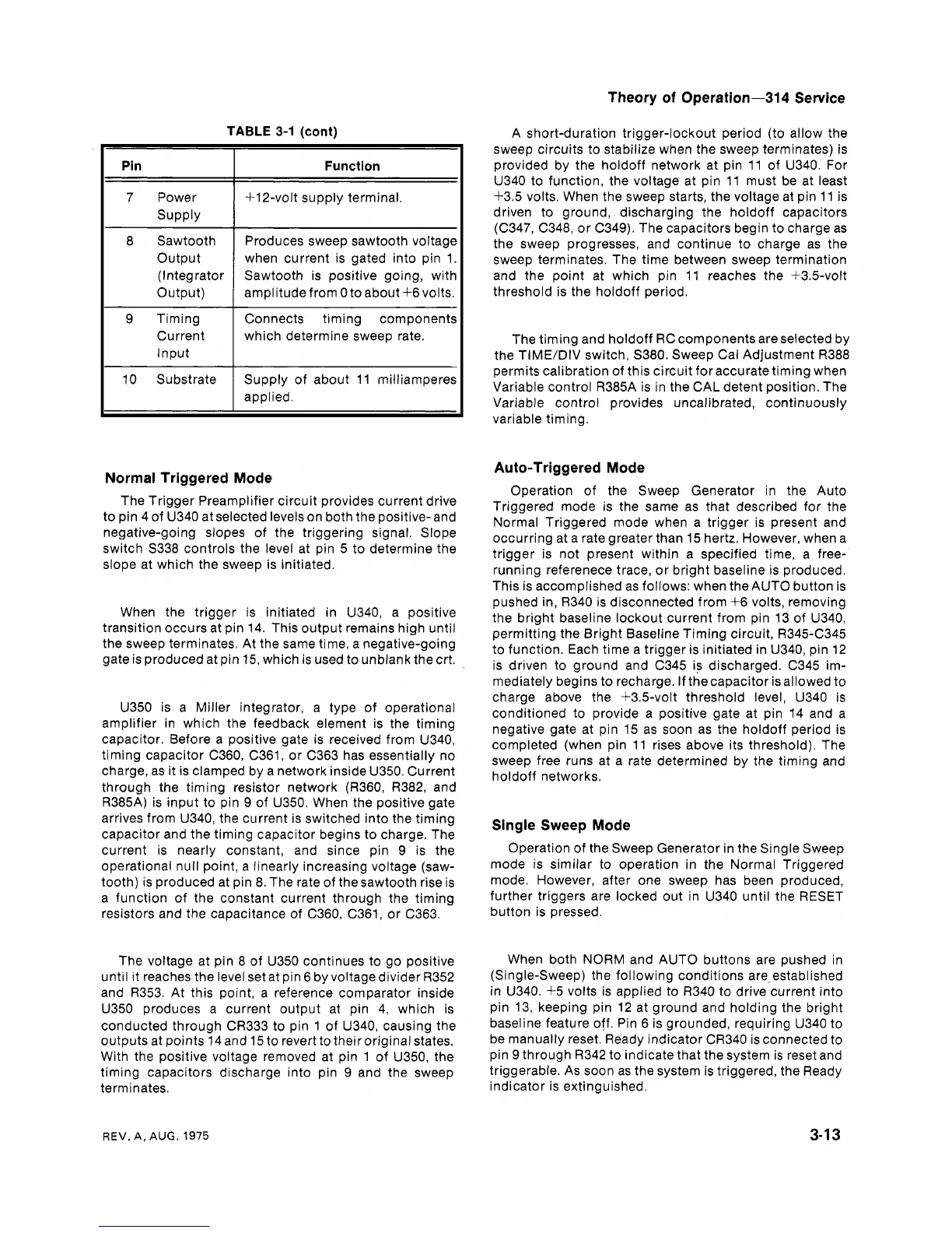
TABLE
3-1
(cont)
Pin
I
Function
I
7 Power
Supply
+12-volt supply terminal.
I
8 Sawtooth
Output
(Integrator
Output)
Produces sweep sawtooth voltage
when current is gated into pin 1.
Sawtooth is positive going, with
amplitude from
0 to about +6volts.
9 Timing
Current
Input
Normal Triggered Mode
Connects timing components
which determine sweep rate.
10 Substrate
The Trigger Preamplifier circuit provides current drive
to pin 4 of U340 at selected levels on both the positive- and
negative-going slopes of the triggering signal. Slope
switch S338 controls the level at pin 5 to determine the
slope at which the sweep is initiated.
Supply of about 11 milliamperes
applied.
I
When the trigger is initiated in U340, a positive
transition occurs at pin 14. This output remains high until
the sweep terminates. At the same time, a negative-going
gate is produced at pin 15, which is used to unblank the crt.
U350 is a Miller integrator, a type of operational
amplifier in which the feedback element is the timing
capacitor. Before a positive gate is received from
U340,
timing capacitor C360, C361, or C363 has essentially no
charge, as it is clamped by a network inside U350. Current
through the timing resistor network (R360, R382, and
R385A) is input to pin 9 of U350. When the positive gate
arrives from U340, the current is switched into the timing
capacitor and the timing capacitor begins to charge. The
current is nearly constant, and since pin 9 is the
operational null point, a linearly increasing voltage (saw-
tooth) is produced at pin 8. The rate of thesawtooth rise is
a function of the constant current through the timing
resistors and the capacitance of
C360, C361, or C363.
The voltage at pin 8 of U350 continues to go positive
until it reaches the level set at pin 6 by voltagedivider R352
and R353. At this point, a reference comparator inside
U350 produces a current output at pin 4, which is
conducted through CR333 to pin 1 of U340, causing the
outputs at points 14 and 15 to revert to their original states.
With the positive voltage removed at pin 1 of U350, the
timing capacitors discharge into pin 9 and the sweep
terminates.
A short-duration trigger-lockout period (to allow the
sweep circuits to stabilize when the sweep terminates) is
provided by the
holdoff network at pin 11 of U340. For
U340 to function, the voltage at pin 11 must be at least
+3.5 volts. When the sweep starts, the voltage at pin 11 is
driven to ground, discharging the holdoff capacitors
(C347, C348, or C349). The capacitors begin to charge as
the sweep progresses, and continue to charge as the
sweep terminates. The time between sweep termination
and the point at which pin 11 reaches the +3.5-volt
threshold is the holdoff period.
The timing and holdoff RC components are selected by
the TIME/DIV switch, S380. Sweep Cal Adjustment R388
permits calibration of this circuit for accurate timing when
Variable control
R385A is in the CAL detent position. The
Variable control provides uncalibrated, continuously
variable timing.
Auto-Triggered Mode
Operation of the Sweep Generator in the Auto
Triggered mode is the same as that described for the
Normal Triggered mode when a trigger is present and
occurring at a rate greater than 15 hertz. However, when a
trigger is not present within a specified time, a free-
running referenece trace, or bright baseline is produced.
This is accomplished as follows: when the AUTO button is
pushed in, R340 is disconnected from
+6 volts, removing
the bright baseline lockout current from pin 13 of
U340,
permitting the Bright Baseline Timing circuit, R345-C345
to function. Each time a trigger is initiated in U340, pin 12
is driven to ground and C345 is discharged. C345 im-
mediately begins to recharge. If thecapacitor isallowed to
charge above the
4-3.5-volt threshold level, U340 is
conditioned to provide a positive gate at pin 14 and a
negative gate at pin 15 as soon as the holdoff period is
completed (when pin 11 rises above its threshold). The
sweep free runs at a rate determined by the timing and
holdoff networks.
Single Sweep Mode
Operation of the Sweep Generator in the Single Sweep
mode is similar to operation in the Normal Triggered
mode. However, after one sweep has been produced,
further triggers are locked out in U340 until the RESET
button is pressed.
When both NORM and AUTO buttons are pushed in
(Single-Sweep) the following conditions
are,established
in U340, +5 volts is applied to R340 to drive current into
pin 13, keeping pin 12 at ground and holding the bright
baseline feature off. Pin 6 is grounded, requiring U340 to
be manually reset. Ready indicator CR340 is connected to
pin 9 through R342 to indicate that the system is reset and
triggerable. As soon as the system is triggered, the Ready
indicator is extinguished.
REV.
A,
AUG.
1975