Theory of Operation-314 Service
TRIGGER
SIGNAL
CH
1
TRIGGER
2
*
S305A
SIGNAL (TRIGGER SOURCE)
CH
2
L
TRIGGER
SIGNAL TO
TRIGGER
PREAMP
TRIGGER
:
*
DISPLAY
SWITCHING
SIGNAL
COMPOSITE
S300
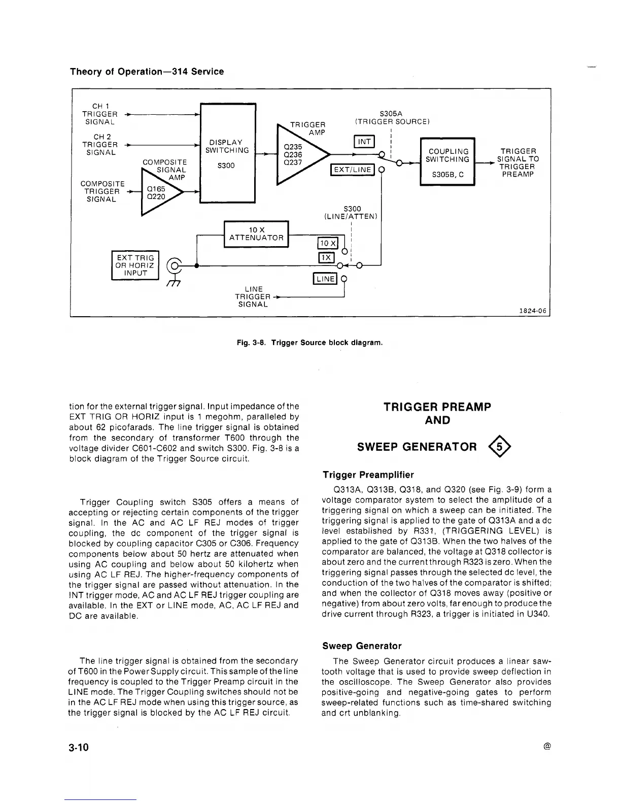
Fig.
3-8.
Trigger Source block diagram.
tion for the external trigger signal. Input impedance of the
TRIGGER PREAMP
EXT TRIG OR HORlZ input is 1 megohm, paralleled by
about 62 picofarads. The line trigger signal is obtained
AND
from the secondary of transformer T600 through the
voltage divider C601-C602 and switch S300. Fig. 3-8 is a
SWEEP GENERATOR
@
block diagram of the Trigger Source circuit.
COUPLING
SWITCHING
S3056,
C
Trigger Preamplifier
-
SIGNAL
5300
(LINEIATTEN)
Trigger Coupling switch S305 offers a means of
accepting or rejecting certain components of the trigger
signal. In the AC and AC LF REJ modes of trigger
coupling, the dc component of the trigger signal is
blocked by coupling capacitor C305 or C306. Frequency
components below about 50 hertz are attenuated when
using AC coupling and below about 50 kilohertz when
using AC LF REJ. The higher-frequency components of
the trigger signal are passed without attenuation. In the
INT trigger mode, AC and AC LF REJ trigger coupling are
available. In the EXT or LlNE mode, AC, AC LF REJ and
DC are available.
10
X
ATTENUATOR
Q313A, Q313B, Q318, and (2320 (see Fig. 3-9) form a
voltage comparator system to select the amplitude of a
triggering signal on which a sweep can be initiated. The
triggering signal is applied to the gate of Q313A and a dc
level established by R331, (TRIGGERING LEVEL) is
applied to the gate of Q313B. When the two halves of the
comparator are balanced, the voltage at Q318 collector is
about zero and the currentthrough R323 iszero. When the
triggering signal passes through the selected dc level, the
conduction of the two halves of the comparator is shifted;
and when the collector of (2318 moves away (positive or
negative) from about zero volts, farenough to produce the
drive current through R323, a trigger is initiated in U340.
I
I
Sweep Generator
LlNE
The line trigger signal is obtained from the secondary
The Sweep Generator circuit produces a linear saw-
of T6OO in the Powersupply circuit. Thissample of the line
tooth voltage that is used to provide sweep deflection in
frequency is coupled to the Trigger Preamp circuit in the
the oscilloscope. The Sweep Generator also provides
LlNE mode. The Trigger Coupling switches should not be positive-going and negative-going gates to perform
in the AC LF REJ mode when using this trigger source, as sweep-related functions such as time-shared switching
the trigger signal is blocked by the AC LF REJ circuit.
and crt unblanking.