Theory of Operation-314 Service
turns off, the positive step at (2555 collector is coupled
through C554 to reset the Sweep Generator.
voltage level slightly, correcting for the deflection-
sensitivity changes that occur when the flood guns are
turned off.
The Q555 "on" time is the sweep reset delay time.
POWER
SUPPLY
@
Integrate
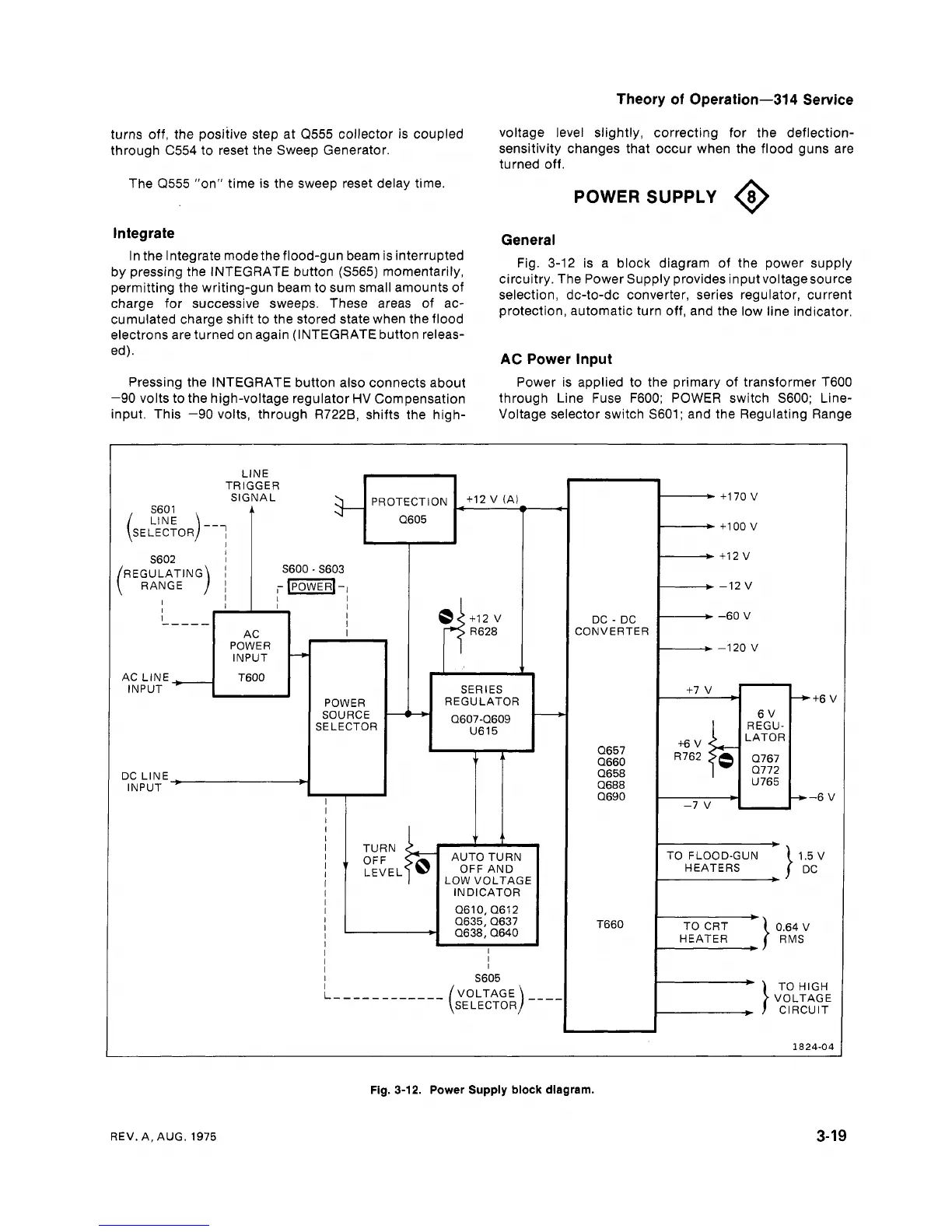
General
Fig. 3-12 is a block diagram of the power supply
circuitry. The Power Supply provides input voltagesource
selection, dc-to-dc converter, series regulator, current
protection, automatic turn off, and the low line indicator.
In the Integrate
modethe flood-gun
beam is interrupted
by pressing the INTEGRATE button (S565) momentarily,
permitting the writing-gun beam to sum small amounts of
charge for successive sweeps. These areas of ac-
cumulated charge shift to the stored state when the flood
electrons are turned on again (INTEGRATE button releas-
ed).
AC
Power Input
Pressing the INTEGRATE button also connects about
-90 volts to the high-voltage regulator HV Compensation
input. This -90 volts, through R7228, shifts the high-
Power is applied to the primary of transformer T600
through Line Fuse
F600; POWER switch S600; Line-
Voltage selector switch S601; and the Regulating Range
LlNE
PROTECTION
+I2
(A)
q-j=
+I70
V
+I
00
v
+I2
V
-12
v
DC
-
DC
-60
V
CONVERTER
TRIGGER
SIGNAL
POWER
INPUT
SERIES
REGULATOR
r-
AC LlNE
INPUT
-
6
V
REGU-
LATOR
0767
0772
U765
POWER
SOURCE
SELECTOR
DC
LlNE
-
INPUT
'
B
AUTO TURN
OFF AND
LOW VOLTAGE
INDICATOR
0610,0612
0635,0637
0638, 0640
TO CRT
0.64
V
HEATER
TO
HIGH
VOLTAGE
CIRCUIT
Fig.
3-12.
Power Supply block diagram.
REV. A, AUG.
1975