Performance CheckICalibration-314 Service
g. Switch CH 1 VOLTS/DIV to 1
m
and return
generator frequency to 50 kHz. Place 10X attenuator
between signal cable and termination.
h. Adjust generator output amplitude for
4
divisions of
vertical display.
a. Connect Square-Wave Generator Fast-Rise,
+
Out-
put through GR to BNC female adapter; 50-ohm cable;
lox, 50-ohm attenuator; 2X, 50-ohm attenuator; and 50-
ohm termination, to CH 1 VERT INPUT connector.
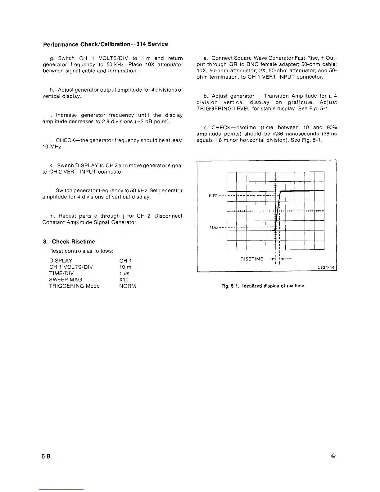
b. Adjust generator
+
Transition Amplitude for a
4
division vertical display on graticule. Adjust
TRIGGERING LEVEL for stable display. See Fig. 5-1.
i. Increase generator frequency until the display
amplitude decreases to 2.8 divisions
(-3
dB point).
c. CHECK-risetime (time between 10 and 90%
amplitude points) should be
<36
nanoseconds
(36
ns
j. CHECK-the generator frequency should be at least
10
MHz.
k. Switch DISPLAY to CH
2
and move generator signal
to CH
2
VERT INPUT connector.
I. Switch generator frequency to 50 kHz. Set generator
amplitude for
4
divisions of vertical display.
m. Repeat parts e through j for CH 2. Disconnect
Constant Amplitude Signal Generator.
8.
Check Risetime
Reset controls as follows:
DISPLAY CH 1
CH
1
VOLTSIDIV
10
m
TIME/DIV 1 I.rs
SWEEP MAG X10
TRIGGERING Mode NORM
equals 1.8 minor horizontal division). See Fig. 5-1.
Fig.
5-1.
Idealized display
of
risetime.