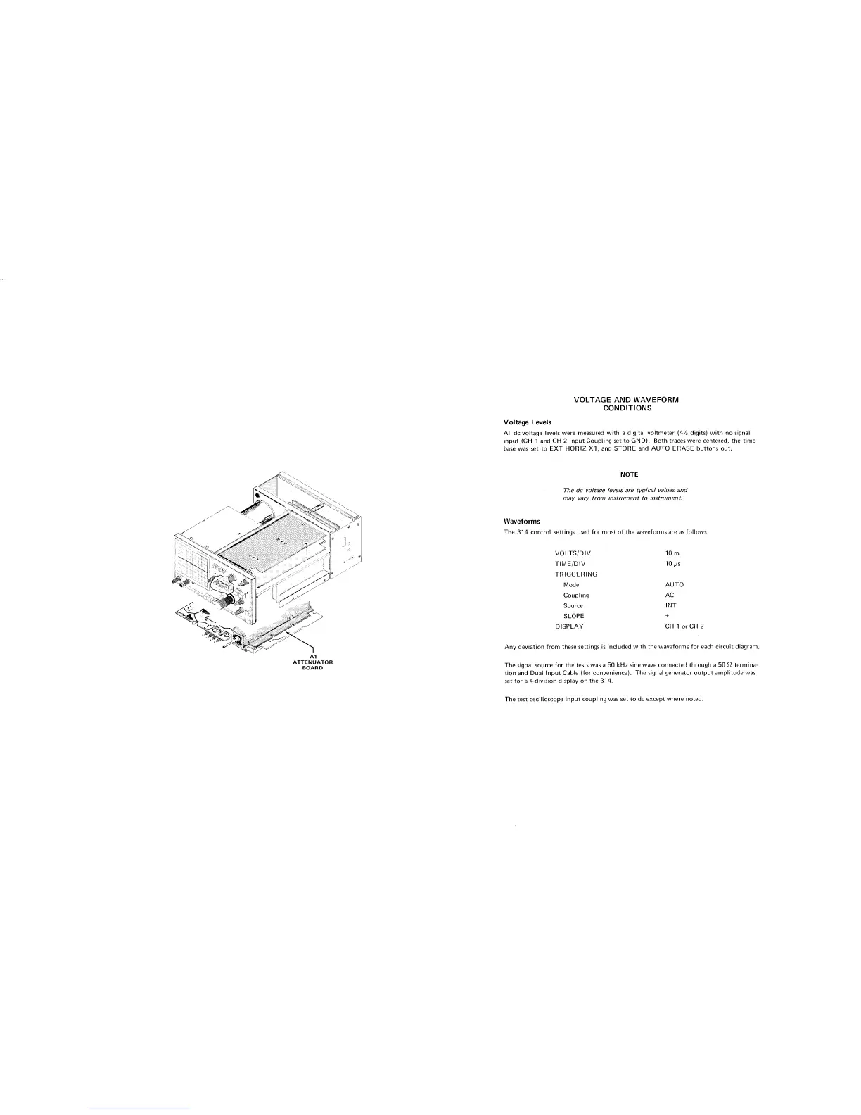
A1
ATTENUATO
R
BOARD
VOLTAGE AND WAVEFORM
CONDITIONS
Voltage Levels
All dc voltage levels were measured with
a
digital voltmeter
(4%
digits) with no signal
input (CH
1
and CH
2
lnput Coupling set to GND). Both traces were centered, the time
base was set to EXT HORlZ XI, and STORE and AUTO ERASE buttons out.
NOTE
The dc voltage levels are typical values and
may vary from instrument to instrument.
Waveforms
The 314 control settings used for most of the waveforms are as follows:
VOLTSIDIV
TIMEIDIV
TRIGGERING
Mode
Coupling
Source
SLOPE
DISPLAY
AUTO
AC
INT
+
CH
1
orCH
2
Any deviation from these settings is included with the waveforms for each circuit diagram.
The signal source for the tests was
a
50
kHz
sine wave connected through
a
50
fi
termina-
tion and Dual lnput Cable (for convenience). The signal generator output amplitude was
set for a 4-division display on the 314.
The test oscilloscope input coupling was set to dc except where noted.