314
Service
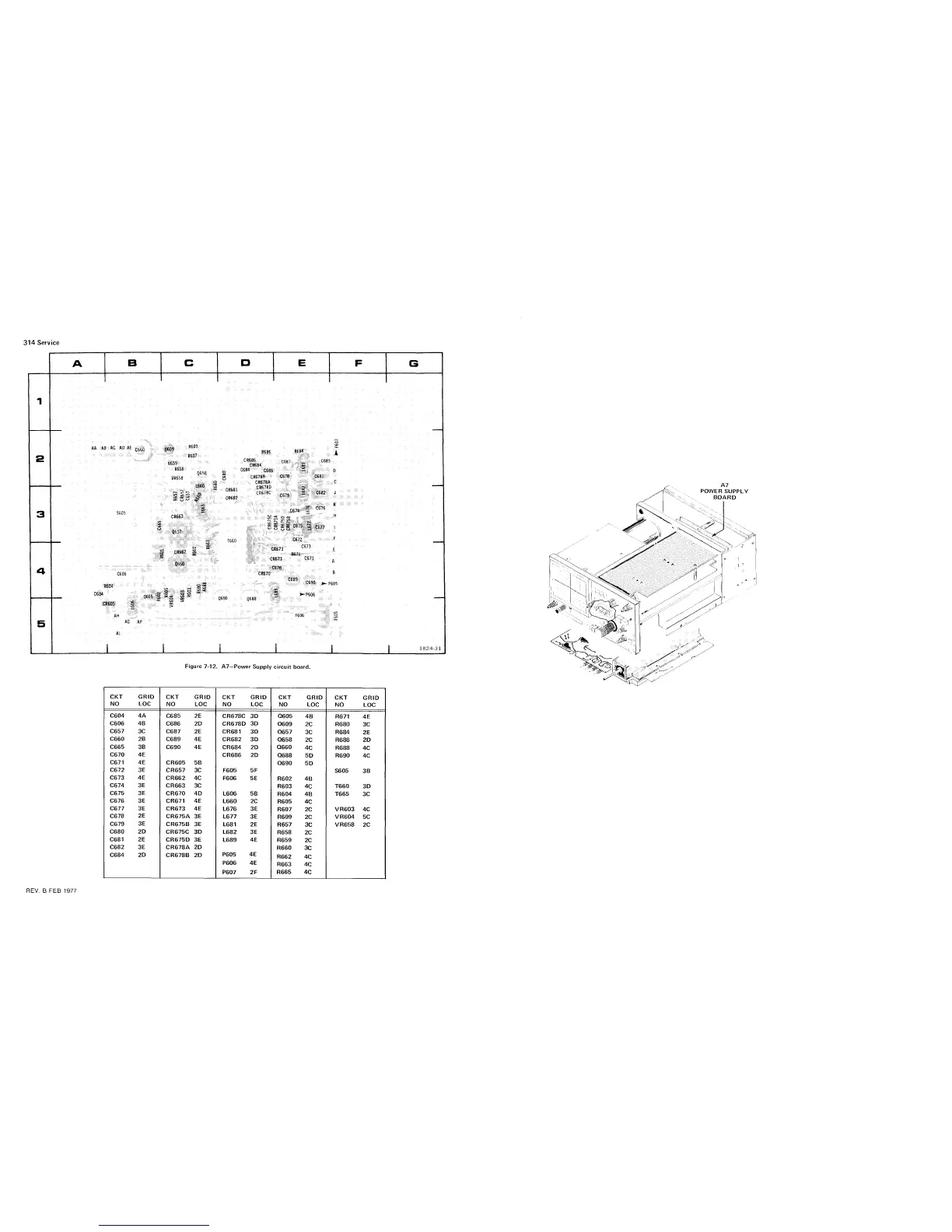
Figure
7-12.
A7-Power
Supply
circuit
board.
CKT
GRlD
NO
LOC
CKT
GRlD
N
0
LOC
C685
2E
C686
2D
C687
2E
C689
4E
C690
4E
REV.
B
FEB
1977
Power Supply Circuit Description
-VR605/Q605 detect overvltage. At about +43v Q605 latches and blows
F600.
-Q605 and associated parts are crowbar overvoltage protection. If +12v rises
above +15 or +27.8 rises above 43 then Q605 latches and blows whichever
fues is supplying power
-U615 regulates in put votage to T660 so that the +12v is +12v
-S605 in 11-14v range uses a different set of taps on T660 and the output
voltage from Q607 will be lower to match.
-Q658 is a constant current bias circuit which powers the inverter
transistors Q657 and Q660.
-Q612 and Q610 shut off the regulator if input voltage falls below 10v.
-Q635/Q637 warn of low input voltage.
 Loading...


