Oporntit~g
Irifortn~tion
314
Sorvico
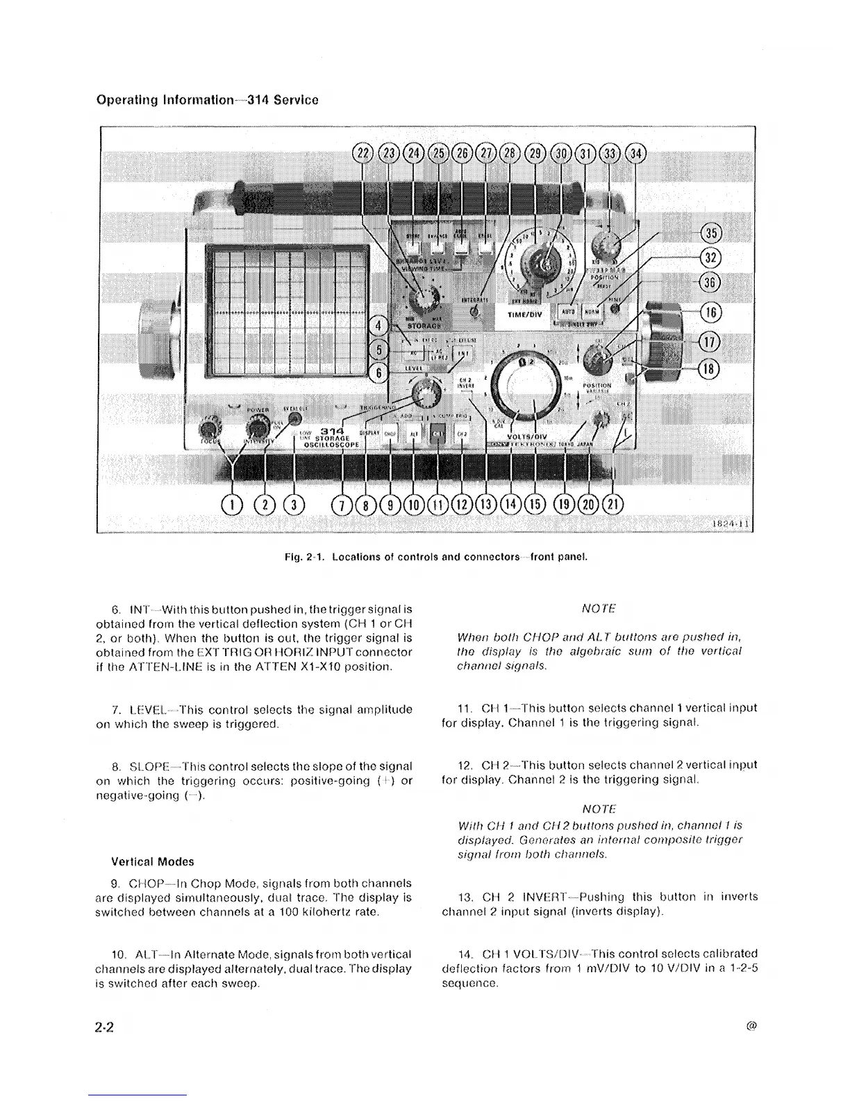
Fie.
2-1.
Locations
of
controls
and
connectors frotit panel.
G
IN'I' With
this
biitton p~tshed
~fi,
the trlgger signal
IS
obtaittcd from the vettical deflection system
(CM
1
or CI
i
2,
or tsothf Whoii the biitton is out,
the
trig~or sigi-taf is
oilta~ned from the
I
X
T
'I'iliG
Of3
t
iOf!I/: INl~JTconnector
tf
the A1.l'EN-LlNf. ts
111
the
Al'i'TN
XI-XfO
position
i'.
i.t:Vf". 'Ithis control selects the signal amplitt~cfe
on which tho sweep
IS
triggered
8
SL
OW l"i?~s control selects tho slope of the stgnal
on
W/IIC~
ftie triggerif?g occtirs
positive~g~tng
f
'
)
or
negative c~oirtcj
(
)
Vertical
Modes
9.
Cf
lOP
in Chop Mock, sigtwls from both ct?annols
are tj~splayocl si~t~uftaneot~sly, cfiiai trace. '1"Iio dtsplay is
swrtched botwcer-1 channels at
a
100
kiloherftr rate.
10
Al
T
In
Alfort-iato Mode, sigtialsfrorrl both vertical
cfiar~itels are dispiayecf alternately, cfual trace 'f'tto display
is switct~ecf after each sweep
11,
Ct
1
I
This btrtton selects ctmnel
1
vertical ~iif~ut
for disj-tlay. Chatinoi
1
IS
the triggering signal.
I?
CI
I
?
'!%is button selects ct~tanr?cl
2
vottical
inpitt
for display Ch8nitcl
2
is tho triggering signal
13
Ci
I
2
INVW
l'
f'l~slliflg thts button itt invcrts
cfiartnel
?
Input signal (invetts cftspfayf
14
Ct
i
I
VOi.
I^Si'I)l\f
I
tris control solocts calibuatod
deflection factors ftot?t
1
rttVif3fV to
10
VIOIV in a
1
.?-5
sequence.