Performance CheckICalibration-314 Service
TRIGGERING SYSTEM
Equipment Required
1. Constant Amplitude Signal Generator
4.
50-ohm Termination
2.
Function Generator
5. 50-ohm Dual Input Cable
3. 50-ohm BNC Cable
6.
50-ohm, 10X Attenuator
Control Settings
DISPLAY
TRIGGERING
Source
Coupling
SLOPE
Mode
TIME/DIV
CH 1 and CH
2
VOLTS/DIV
STORE
CH 1
I NT
AC
+
NORM
10 ps
10 m
out
1.
Check Triggering Levels
a. Connect Constant Amplitude Signal Generatorout-
put through GR-to-BNC female adapter; 50-ohm cable;
lox, 50-ohm attenuator; 50-ohm termination; and dual
input cable, to CH
1
VERT INPUT connector and EXT
TRIG OR HORlZ INPUT.
b. Set generator frequency to 1 MHz and output
amplitude to produce a 0.3-division vertical display on crt.
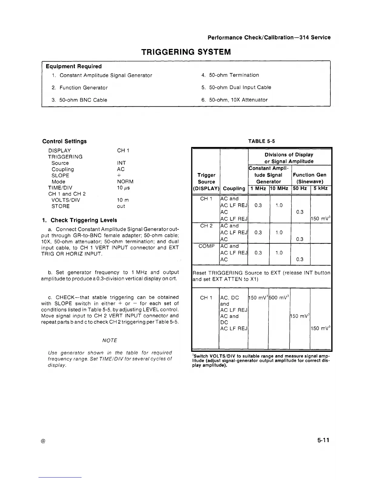
c. CHECK-that stable triggering can be obtained
with SLOPE switch in either
+
or
-
for each set of
conditions listed in Table 5-5, by adjusting LEVEL control.
Move signal input to CH
2
VERT INPUT connector and
repeat parts b and c to check CH
2
triggering perTable 5-5.
NOTE
Use generator shown in the table for required
frequency range. Set TIMEIDIV for several cycles of
display.
TABLE 5-5
leset TRIGGERING Source to EXT (release INT button
nd set EXT ATTEN to XI)
Trigger
Source
DISPLAY)
CH 1
CH
2
COMP
CH 1 AC, DC 150 mv3
and
AC LF REJ
AC and
DC
AC LF REJ
'6
lil
play amplitude):
-
Coupling
AC and
AC LF REJ
AC
AC LF REJ
AC and
AC LF REJ
AC
ACand
AC LF REJ
AC
switch
VOLTS/DIV
to suitable range and measure signal amp-
tude (adjust signal-generator output amplitude for correct dis-
Divisions of Display
or Signal Amplitude
Constant Ampli-
tude Signal
Generator
1 MHz
0.3
0.3
0.3
Function Gen
(Sinewave)
10 MHz
1
.O
1
.O
1
.O
50 Hz
0.3
0.3
0.3
5
kHz
150 mv3