Performance CheckICalibration-314 Service
TABLE
5-6
c. Set DISPLAY to CH 1, CH 1 Input Coupling to DC,
and CH 1 VOLTS/DIV to 10 m.
VOLTWDIV CH
1
CH
2
Settings Corner
1
Flat Top
1
Corner
I
Flat Top
d. Set Square-Wave Generator Fast-Rise output
amplitude for 4 divisions of vertical display (use 2X
attenuator between cable and termination, if necessary).
Set TIME/DIV to display
3
or
4
cycles of square-wave.
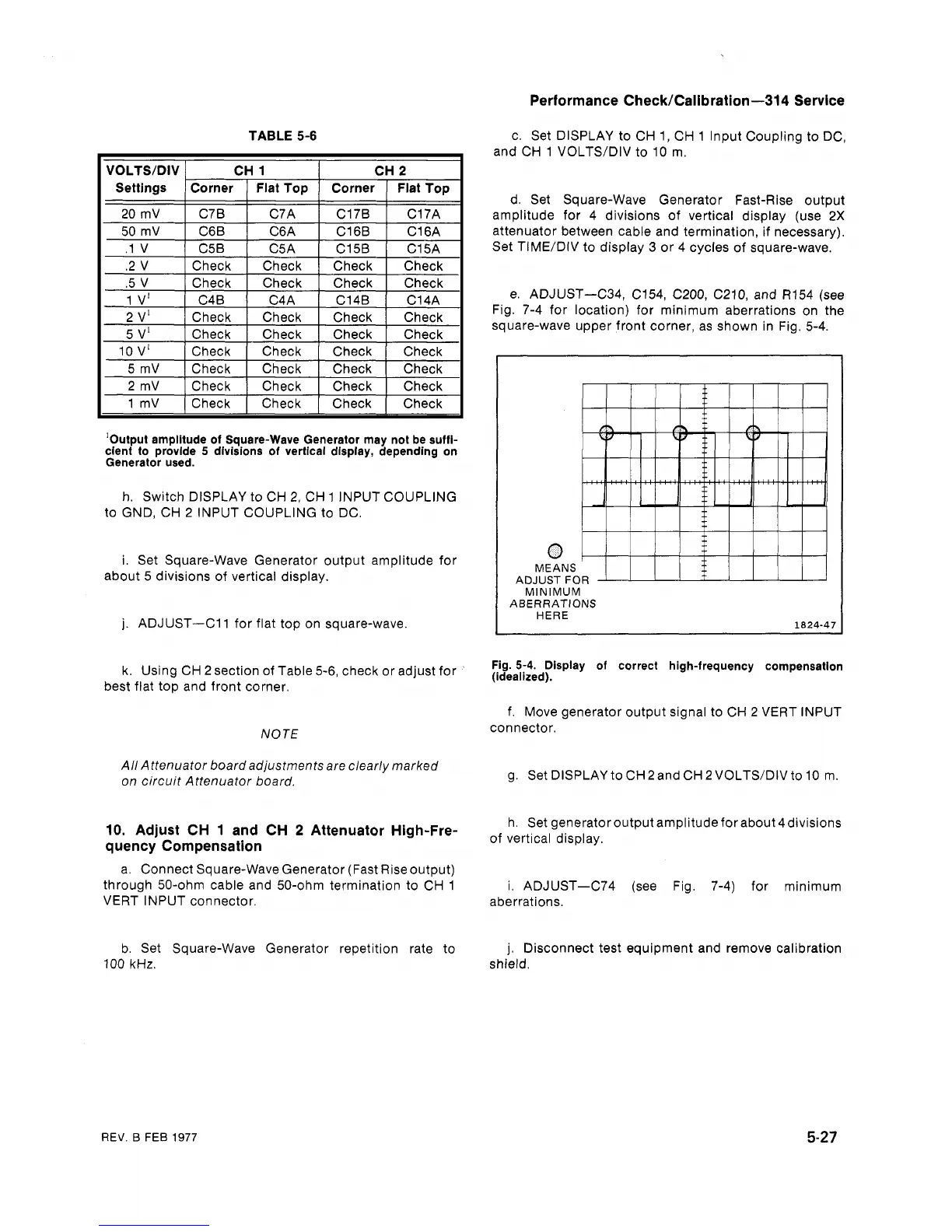
e. ADJUST-C34, C154, C200, C210, and R154 (see
Fig. 7-4 for location) for minimum aberrations on the
.2 V
.5 V
1
V'
2
v1
square-wave upper front corner, as shown in Fig. 5-4.
5
v1
1
Check
I
Check
I
Check
I
10
V'
1
Check
1
Check
1
Check
1
Check
Check
Check
C4B
Check
5
mV
1
Check
I
Check
I
Check
I
Check
I
2
mV
1
Check
I
Check
I
Check
I
Check
I
Check
Check
C4A
Check
1 mV
1
Check
I
Check
I
Check
1
Check
I
'Output amplitude of Square-Wave Generator may not be suffi-
cient to provide
5
divisions of vertical display, depending on
Generator used.
Check
Check
C14B
Check
h. Switch DISPLAY to CH
2,
CH 1 INPUT COUPLING
to GND, CH
2
INPUT COUPLING to DC.
Check
Check
C14A
Check
0)
MEANS
ADJUST FOR
i. Set Square-Wave Generator output amplitude for
about
5
divisions of vertical display.
I
MINIMUM
ABERRATIONS
I
HERE
j.
ADJUST-Cl1 for flat top on square-wave.
Fig.
5-4.
Display of correct high-frequency compensation
(idealized).
k. Using CH 2 section of Table 5-6, check or adjust for
best flat top and front corner.
f. Move generator output signal to CH
2
VERT INPUT
connector.
NOTE
All Attenuator board adjustments are clearly marked
on circuit Attenuator board.
g. Set DISPLAY to CH 2 and CH 2 VOLTWDIV to 10 m.
h. Set generator output amplitude for about
4divisions
of vertical display.
10.
Adjust CH
1
and CH
2
Attenuator High-Fre-
quency Compensation
a. Connect Square-Wave Generator (Fast Rise output)
through 50-ohm cable and 50-ohm termination to CH 1
VERT INPUT connector.
i. ADJUST-C74 (see Fig. 7-4) for minimum
aberrations.
b. Set Square-Wave Generator repetition rate to
100 kHz.
j.
Disconnect test equipment and remove calibration
shield.
REV.
B
FEB
1977