Reference
370B User Manual
3-49
Measuring Examples
This part of this section describes the use of the 370B to measure some basic
parameters of bipolar transistors, field effect transistors, silicon controlled
rectifiers, signal and rectifier diodes, Zener diodes. For each of the devices
discussed, this section includes tables of 370B control settings required to make
an accurate measurement without damaging the device under test. Below each
table is a block diagram showing the connections of the collector supply, the step
generator and the display amplifiers to the device under test, and a picture of a
typical characteristic for the semiconductor type being discussed. Also included
is a list of common measurements that may be made on the given devices with
the 370B and a brief set of instructions on how to make each of these measure-
ments.
This section has been written with the assumption that you are familiar with the
operation of the 370B as described at the beginning of this section. It is also
assumed that you are familiar with the parameters under discussion.
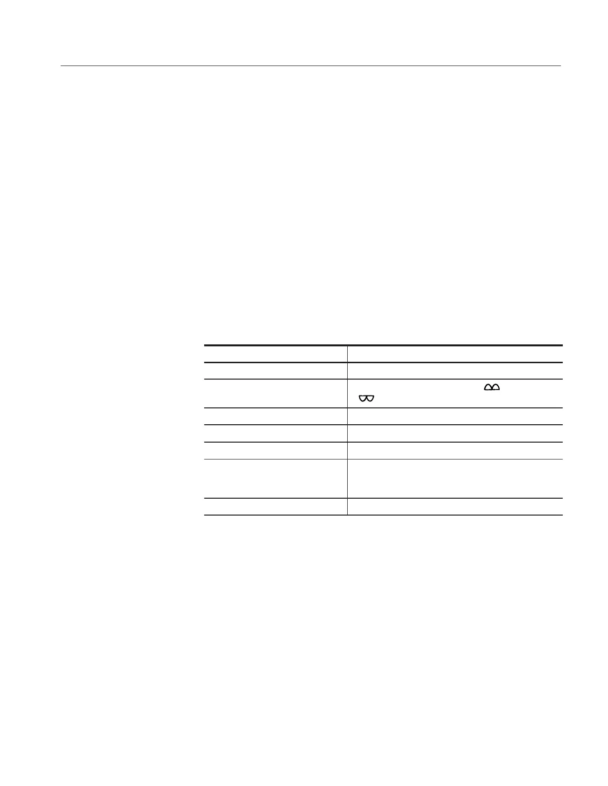
Control Required Setting
HORIZONTAL COLLECTOR
COLLECTOR SUPPLY POLARITY For the Common-Emitter Family, + or
- depending on the transistor type.
MAX PEAK POWER WATTS Less than maximum power rating of device.
STEP GENERATOR OUTPUT CURRENT
PULSE Set to LONG or SHORT when using high base current
CONFIGURATION EMITTER COMMON BASE STEP GEN for common-
emitter family, BASE COMMON EMITTER STEP GEN
for common-base family.
STEP GENERATOR AID pressed if more than 10 steps are desired.
Bipolar Transistor