Reference
370B User Manual
3-7
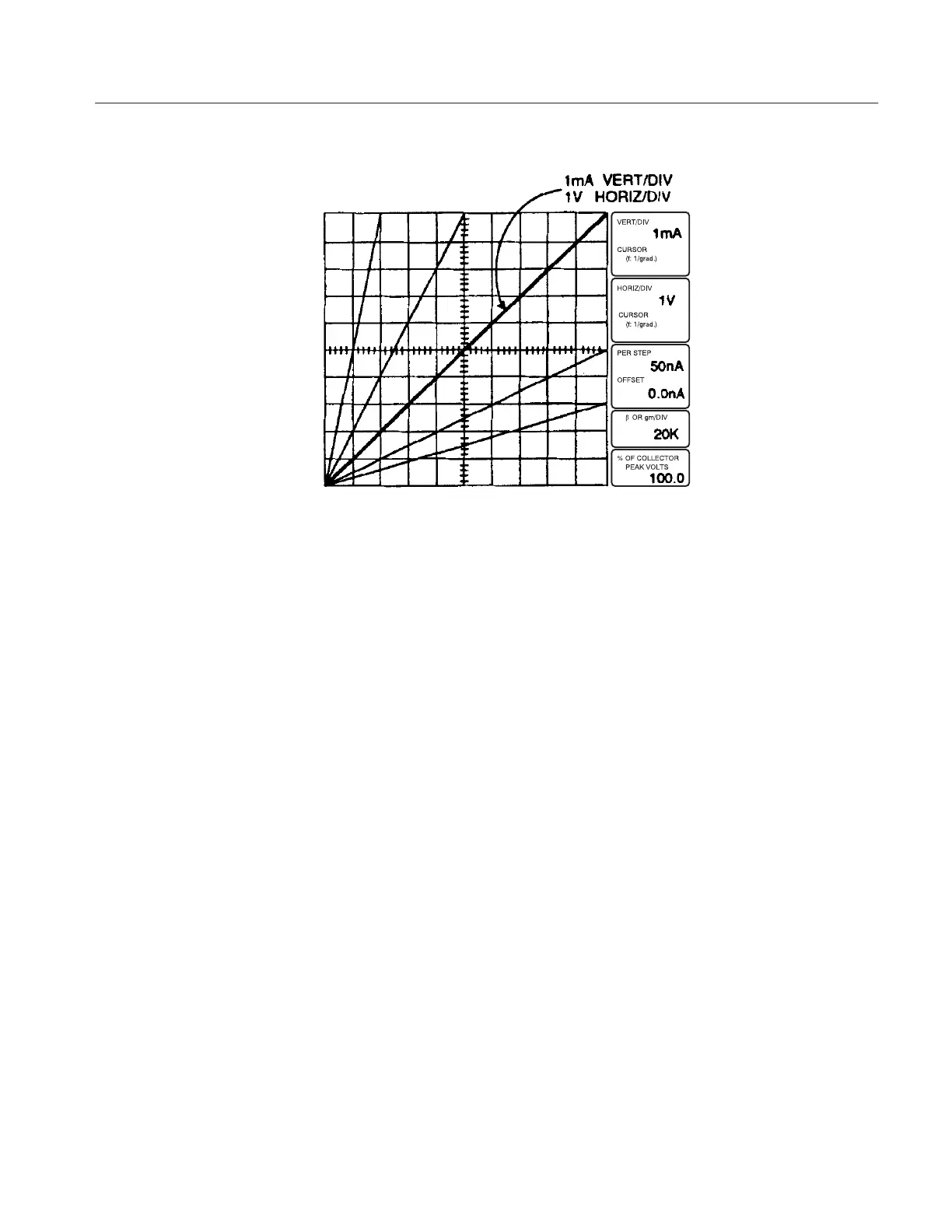
Figure 3-2: Display of I vs. E for 1 k resistor
7. Rotate the HORIZONTAL control clockwise and note that as the horizontal
deflection factor decreases, the line slope decreases (see Figure 3–2). Turn
the HORIZONTAL control counterclockwise from the 1 V position and
note the change in slope. Also note that the HORIZ/DIV readout changes as
the HORIZONTAL control is rotated. Reset the HORIZONTAL control to
1 V.
8. Press DISPLAY INVERT (red LED turns on) and rotate the VARIABLE
COLLECTOR SUPPLY control first counterclockwise, then clockwise.
Note that the display is now inverted and originates in the upper right corner
of the graticule. Press the DISPLAY INVERT button (red LED turns off).
1. Turn the VARIABLE COLLECTOR SUPPLY control until the diagonal
trace reaches graticule center. Set the MAX PEAK POWER WATTS to
220. Note that the diagonal trace lengthens as the wattage is increased. Refer
to the SERIES RESISTORS TABLE on the front panel. Note that the series
resistor decreases as the maximum peak power is increased.
2. Set the OUTPUTS breaker to the DISABLE position, then open the
protective cover.
3. Replace the resistor in the axial lead adapter with a silicon diode. Connect
the diode to the axial lead adapter . Close the protective cover.
4. Observe that the Memory Index is set to 1, then press the Setup RECALL
button.
Collector Supply
 Loading...