Operating Basics
370B User Manual
2-13
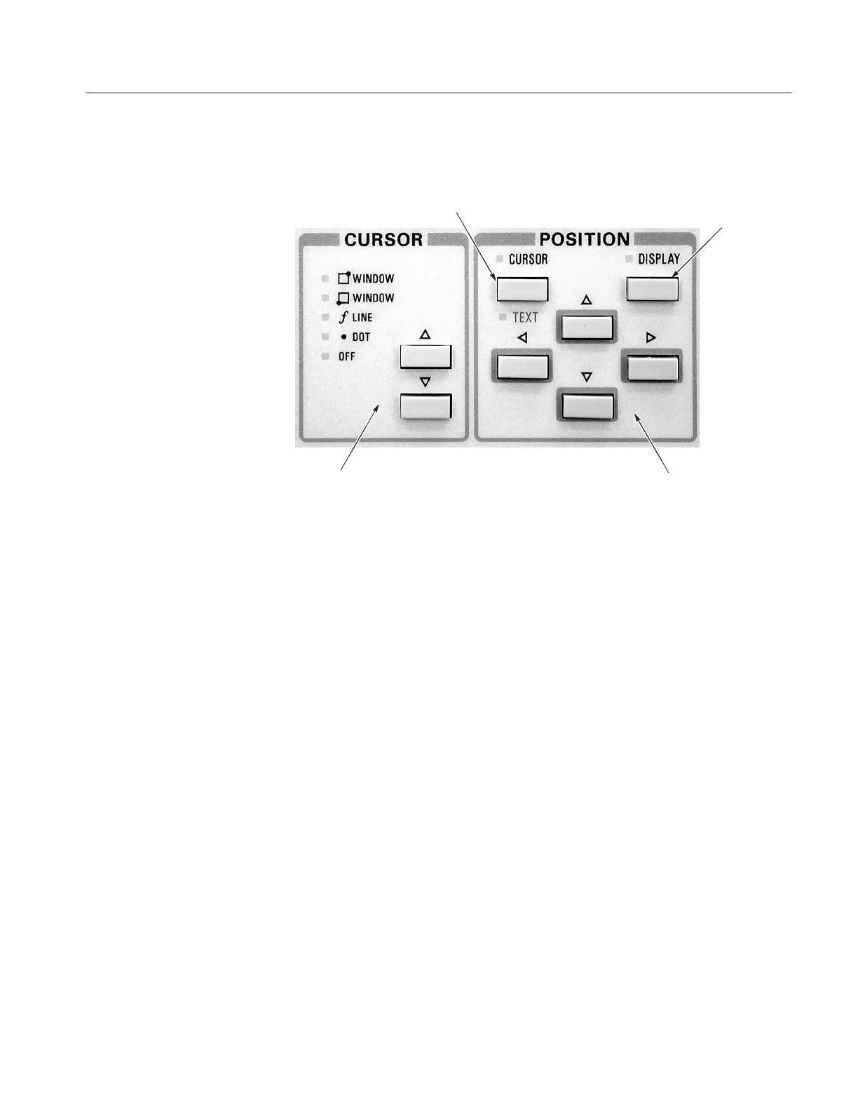
Figure 2–5 shows the Cursor and Position controls.
Figure 2-5: Cursor and Position Controls
CURSOR SELECTION. The CURSOR SELECTION mode selects one of the
three types of cursors:
DOT. The DOT cursor is a high-intensity dot displayed on the trace. The
voltage and current at the DOT cursor position are indicated in the CURSOR
readout area. The DOT cursor can be positioned with the four Position
Control buttons. It can also be used to measure DC b.
If the DOT cursor is positioned off-screen, both the vertical and horizontal
CURSOR readouts blink. When REF curve is displayed, the DOT cursor is
displayed only on the STORE or VIEW curve. In NON STORE display
mode, the DOT cursor is not displayed.
f LINE. The f LINE (functional line) cursor is a straight line which passes
through the DOT cursor position at a slope that can be changed by the four
Position Control buttons. The slope is indicated in the CURSOR (f:
1/gradient) area of the readout.
The point at which the f LINE cursor intercepts the horizontal axis is
indicated in the CURSOR (f:intercept) area of the readout, giving the
horizontal coordinate value.
The f LINE cursor can be used to measure the “on” resistance or horizontal
intercept voltage of the device.
Cursor and Position
Controls