Reference
3-10
370B User Manual
17. Reduce the intensity, then reset the following controls:
LEFTĆRIGHTĆSTANDBY LEFT
Display Mode NON STORE
VERTICAL CURRENT/DIV 1 mA
HORIZONTAL VOLTS/DIV 2V
Collector Supply POLARITY AC
MAX PEAK VOLTS 16
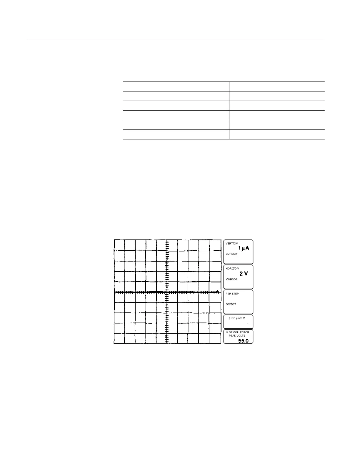
18. Turn the VARIABLE COLLECTOR SUPPLY control to 100%, adjust the
trace intensity for a visible display, and adjust the LOOPING COM-
PENSATION control for minimum trace width (see Figure 3–5). Use the
TRACE ROTATION control to align the trace with the horizontal graticule
line.
19. Set the OUTPUTS breaker to the DISABLED position, then open the
protective cover.
20. Replace the diode in the axial lead adapter with an Zener diode. Connect the
diode cathode to the emitter terminal. Close the protective cover.
Figure 3-5: Adjustment of LOOPING COMPENSATION control
21. Observe that the Memory Index is set to 1, then press the Setup RECALL
button to initialize the 370B.