GPIB
4-10 370B User Manual
Setup
The first steps in putting the 370B to work in a system are:
Setting the bus address
Choosing the message terminator
Connecting the GPIB cable
Powering up
These steps are discussed in the following paragraphs.
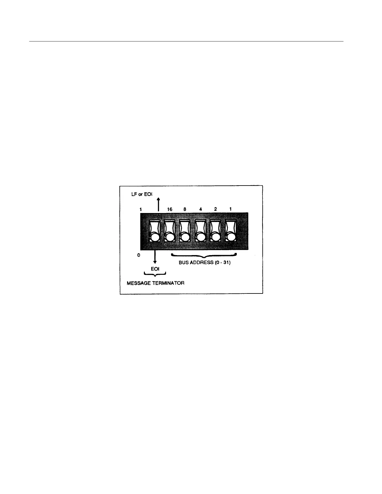
The 370B has a configuration switch bank on the rear panel which is used to set
the bus address and message terminator (see Figure 4–3).
Figure 4-3: Rear panel configuration switch
Setting the Bus Address. Each instrument connected to the bus must have a
unique address. This address is used by the controller to direct the flow of data to
and from that specific device.
When choosing a bus address for the instrument, remember:
The address of the 370B must be unique on the bus.
Some controllers reserve an address for themselves.
Selecting an address of 31 logically removes the 370B from the bus; it does
not respond to any GPIB address, but remains both unlistened and untalked.
The 370B uses primary addressing only. Sending a secondary address will
have no effect.
Configuration Switch
Settings
 Loading...