Appendix A: Specifications
A-6 370B User Manual
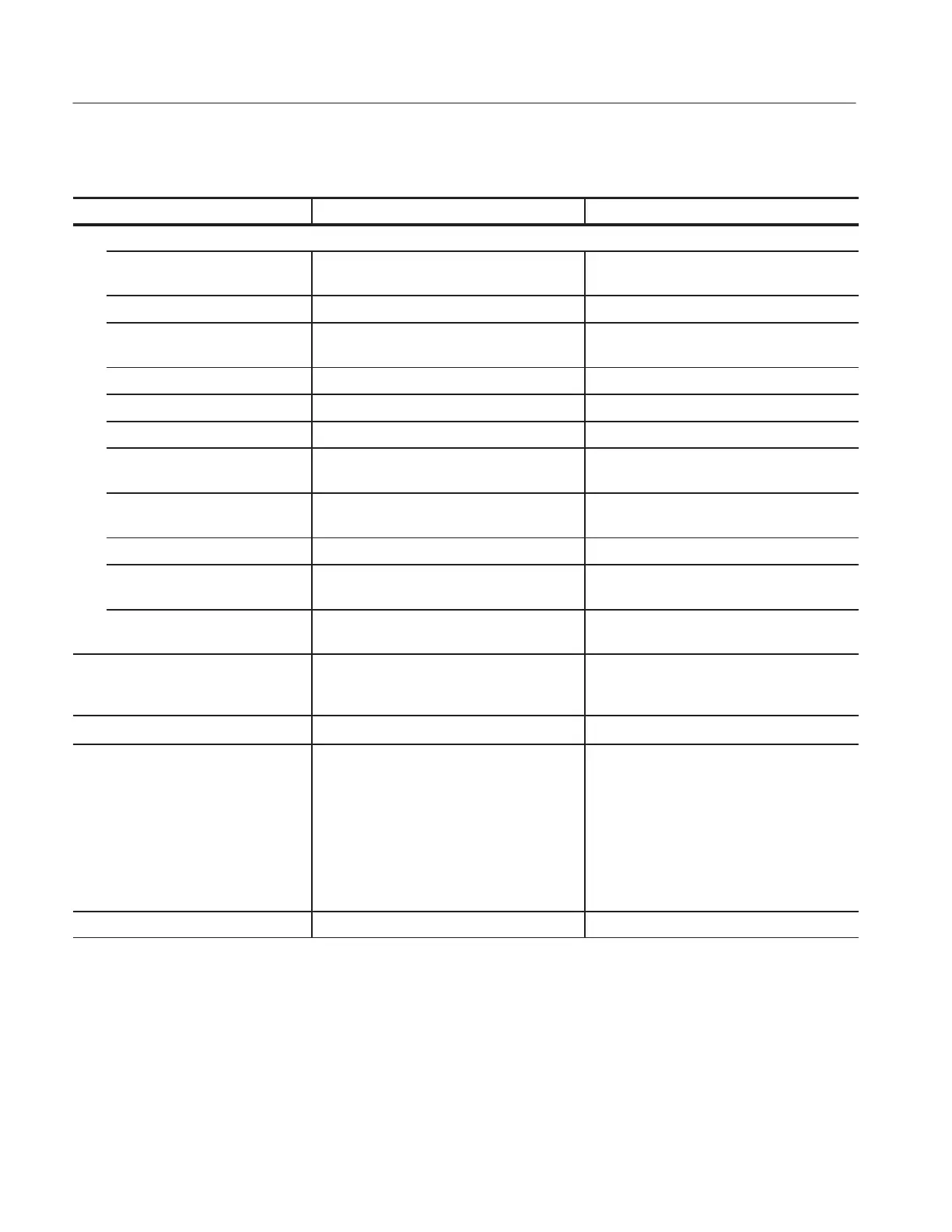
Table A-2: Step Generator (Cont.)
Characteristic Operating InformationPerformance Requirement
Voltage Mode
Amplitude switch range 50 mV to 2 V, in a 1-2-5 sequence of 6
steps
Maximum voltage 20 x STEP AMPLITUDE
Maximum current At least 500mA at 10V or less, at least
200mA at 15 V, at least 10 mA at 40 V.
2
Short circuit current limiting 500 mA, +50%, -20%
Maximum opposing offset volts 10 x STEP AMPLITUDE
Maximum opposing current Less than 20 mA
Ripple plus noise Less than 0.5% x STEP AMPLITUDE
+10mV
BW = 20 MHz, with open circuit.
Maximum capacitive load
(typical)
0.01 mF
Output Impedance (typical) 200 mW or less
Fall and rise time (typical) Within 50 ms for 1 step or 100 ms for 10
steps. 1 kW load, 2 V/step.
1kW load at 2 V/step
Overshoot (typical) Within 10 % of transition amplitude. 1 kW
load, 2 V/step.
1kW load at 2 V/step
Step rates 2 x line frequency (1 x line frequency in AC
collector supply mode). Steps occur at 0
collector voltage.
Pulsed steps
80 msor300ms wide, "10 %
At mesial line, with 1 kW load, 1 mA /STEP
Steps and offset polarity Corresponds to Collector Supply Polarity
when STEP GENERATOR POLARITY
INVERT is disabled.
Opposite to Collector Supply Polarity when
STEP GENERATOR POLARITY INVERT is
selected or CONFIGURATION switch is set
to BASE COMMON.
BASE COMMON configuration disables
STEP GENERATOR POLARITY INVERT.
Number of steps Ranges from 0 to 10.
 Loading...