Reference
3-20
370B User Manual
44. Press and hold the OFFSET AID button until a step is just visible on the
CRT, and note the offset value (approximately 500 mV). The OFFSET
readout indicates the base-to-emitter voltage of the transistor.
1. Change the Memory Index to 2, then press the Setup RECALL button.
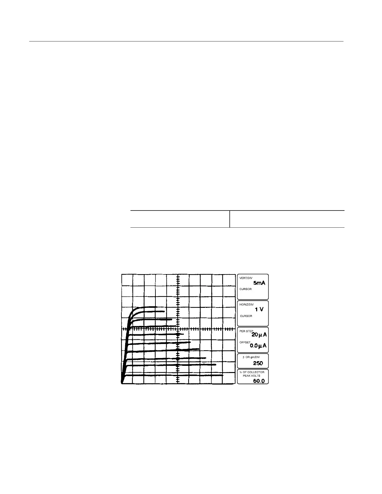
2. Note the display of characteristic curves with the emitter grounded and
current steps applied to the base (see Figure 3–15).
3. Set the OUTPUTS breaker to the DISABLED position, then open the
protective cover. Connect a patch cord with banana plugs on each end
between the STEP GEN OUT connector and the EXT BASE or EMITTER
IN connector.
4. Close the protective cover.
5. Change the following 370B setting:
6. Set the OUTPUTS breaker to the ENABLED position, then turn the
VARIABLE COLLECTOR SUPPLY control slowly clockwise. Note a
display similar to that seen in Step 2.
Figure 3-15: CONFIGURATION control set to BASE STEP GEN (NORM)
7. Set the OUTPUTS breaker to the DISABLED position, then open the
protective cover. Remove the patch cord.
Configuration