Reference
3-22
370B User Manual
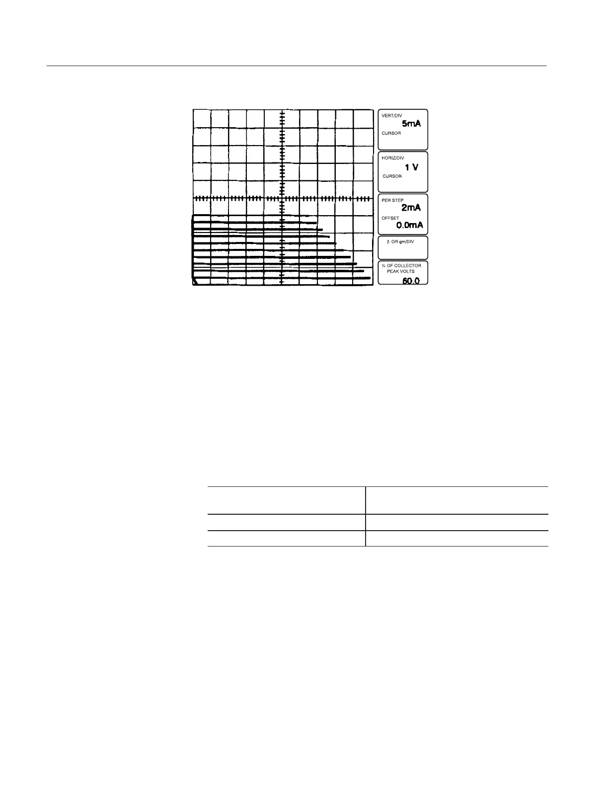
Figure 3-16: CONFIGURATION control set to EMITTER STEP GEN
19. Set the OUTPUTS breaker to the ENABLED position.
20. Turn the VARIABLE COLLECTOR SUPPLY control clockwise and note
a display similar to that seen in step 15.
21. Set the OUTPUTS breaker to the DISABLED position, then open the
protective cover. Remove the patch cord.
22. Close the protective cover.
23. Change the following 370B settings:
! "#
24. Set the OUTPUTS breaker to the ENABLED position.
25. Turn the VARIABLE COLLECTOR SUPPLY control clockwise and note
the base leakage current display with the collector terminal open.