Troubleshooting
Checking the Power
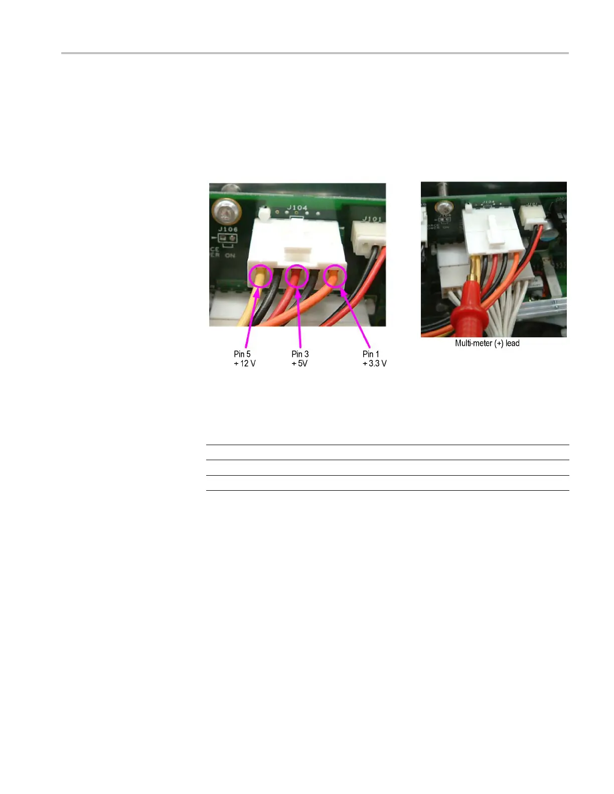
Supply Voltages
To check the pow
er supply voltages, power on the instrument and connect the (–)
lead of a multimeter to chassis ground.
To measure the
output voltages of the power supply, check the voltages at J104
on the PWR board with the multimeter and compare each reading to the values
listed in the following table. If the voltages are within the allowance, your power
supply is functional.
Figure 4-27: PWR board test points
Table 4-4: Power supply voltages
PWR board (J104) Voltage Allowance
Pin1 +3.3 V +3.1 V to +3.5 V
Pin 3 +5 V +4.7 V to 5.3 V
Pin 5 +12 V +11.4 V to +12.6 V
AWG7000B and AWG7000C Series Service Manual 4–55

 Loading...


